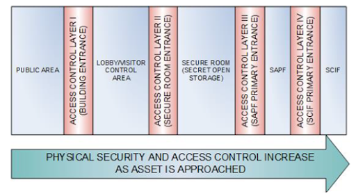
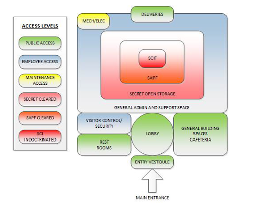
Special Access Program Facilities (SAPFs) are specialized spaces that satisfy the criteria for generating, safeguarding, handling, discussing, and storing classified or unclassified program materials.
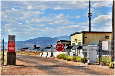
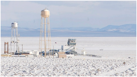
Famous SAPFs include Area 51, the Sandia National Laboratories, Tonopah Test Range, and Lockheed Skunk Works (Palmdale Plant 42).
Similar to SCIFs (Sensitive Compartmented Information Facilities) SAPFs are classified based on operational requirements.
SAPF classifications include:
- Continuous Operation Facilities (i.e. Accredited facilities staffed and operated 24/7),
- Open Storage Facilities (i.e. Accredited facilities in which Sensitive Compartmented Information or Special Access Program information may be openly stored or processed without use of U.S. General Services Administration-approved storage containers),
- Closed StorageFacilities (i.e. Accredited facilities where Sensitive Compartmented Information or Special Access Program material is required to be stored in U.S. General Services Administration-approved storage containers when not in use.)
SAPFs include new structures and temporary areas built in existing structures. SAPFs include facilities within the United States and outside the United States.
That said, SAPFs typically include the penultimate zone of highest security in a new or existing structure.
More permanent SAPFs, namely Continuous Operation facilities, Open Storage facilities, and Closed Storagefacilities can be incredibly complex structures, requiring special attention to detail throughout design and construction.
Governing SAPF design codes and standards include the Intelligence Community Directive (ICD) 705 standard, the Unified Facilities Criteria (UFC) No. 4-010-05, (UFC 4-010-05) SCIFF/SAPF Planning, Design, and Construction standard.
For SAPF design and construction in high-risk areas, governing design codes and standards include the International Building Code (IBC),the Unified Facilities Criteria (UFC) No. 4-010-01 (UFC 4-010-01), DoD Minimum Antiterrorism Standards for Buildings and the UFC 4-023-03, Design of Buildings to Resist Progressive Collapse.
For SAPF Construction-Defect Plaintiff Litigators, identifying the extent a construction defect and/or design defect, while accurately estimating projected repair costs can prove to be a daunting process. This is most notable for litigators citing construction and design standard-of-care violationsand/or defective material quality.
Below are 5 top structural blind spots in SAPF Design and Retrofit Projects for Construction-Defect Defense Litigators
For construction defects or design defects involving structural components it is generally advisable to engage construction-defect and structural forensic engineering experts early on in the case to determine causation, reduce risks, and limit costs.
Preeminent Solutions is a DBE-certified, MWBE-certified, LDB-certified and soon to be 8(a)-certified and WOSB-certified, civil/structural engineering firm specializing in structural forensics and construction-defect expert witness work.
Contact us for your next SAPF Construction-Defect case.
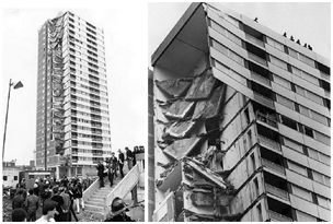
Progressive-Collapse requirements
SAPFs in high-risk regions (i.e. regions prone to terrorist attacks) require antiterrorism upgrades, namely progressive collapse resistance, to reduce collateral damage and to mitigate the scope and severity of mass casualties.
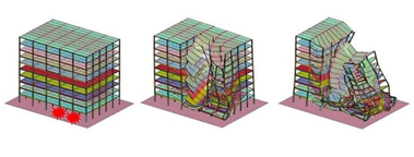
Progressive collapse resistance includes design and construction practices intended toreduce the potential of progressive collapse (i.e. the spread of a local failure from one element to another)for structures that experience localized structural damage through generally unanticipated events.
Protective structural design generally allows for three methods to increase progressive collapse resistance:
The Tie Force Approach (i.e. the method in which the building is mechanically tied together, thus enhancing continuity and ductility.)
Structural Redundancy(i.e. the structure’s ability to provide alternative means ofresisting applied loads.)
Structural Target Hardening (i.e. performance improvements, namely strength improvements, stiffness, and ductility improvements ofindividual structural components.)
Some existing structuresare not ableto readily accommodate all recommended antiterrorism upgrades, particularly tie forces.
Key signs of low structural ability to accommodate tie-forces include:
- Weak or Brittle Connections
- Discontinuous Floor Slabs
- Discontinuous Roof Slabs
- Deteriorated Beams, Girders or Spandrels (i.e. Members that cannot withstand longitudinal, transverse, or peripheral tie force magnitudes while undergoing rotations of 11.3-deg)
Acceptable floor and roof systems (i.e. systems that typically accommodate tie forces well) includecast-in-place concrete and composite decks.
Contact a qualified structural engineer if your structure displays any of the above signs of poor structural redundancy.
Likewise, consult a qualified blast consultant should your structure require antiterrorism retrofits.
Tornado Missile Resistance
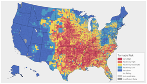
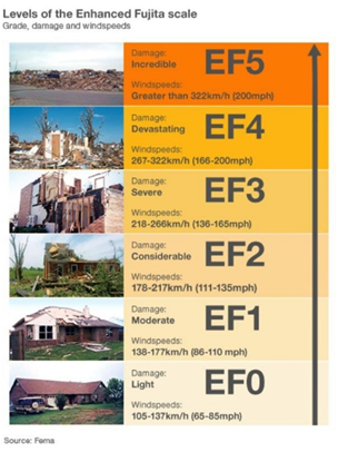
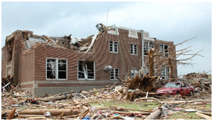
Regularly SAPF new-builds and/or pre-existing structures are situated in areas with high tornado missile-risk, due to Hurricanes, Tornados, and/or similar windstorms.
In high tornado missile-risk regions, SAPFs must maintain robust perimeters (i.e. perimeter walls, roofs, etc.)
Per the 2024 International Building Code (IBC) Code, the governing code on the matter at time of this publication, the design and construction of Risk Category III and IV buildings and other structures located in tornado-prone regions structures shall be done in accordance with ASCE 7.
Due to the threat to life and public safety it is imperative that structures are able to withstand design tornado-missile load demands, particularly in tornado-prone regions.
Key signs of high tornado missile-risk susceptibility (i.e. poor tornado missile-risk resistance) in buildings include:
- Lack of Structural Redundancy
- Unreinforced or Under-reinforced Masonry Walls
- Unreinforced or Under-reinforced Brick Veneer
- Insufficient Stud Spacing
- Missing or Under-designed Hurricane Strap Connections
- Discontinuous Vertical and Horizontal Load Paths
- Loose and/or Degraded Roof Decking
- Loose and/or Degraded Exterior Wall Panels
- Corroded / Deteriorated Connection Fasteners
- Corroded / Deteriorated Anchorage to Foundation
- Bowing and/or Leaning Columns and Walls (particularly at corners of structure.)
Tornado missiles provide a threat to life and safety and property. As a consequence, it is generally advised to maintain a base level of structural redundancy to accommodate for unintended tornado-missile loads.
Note: Structural redundancy includes the structure’s ability to provide alternative means of resisting applied loads.
Key signs of low structural redundancy include:
- Singular Column Supports with Larger Tributary Areas and Heightened Loads Instead of Multiple Column Supports
- Singular or Fewer Beams with Larger Tributary Areas and Heightened Loads Instead of Multiple / More Beams
- Weak or Brittle Connections
- Lack of Neighboring or Alternative Load Paths.
Key signs of tornado-missile damage in buildings include:
- Concrete Chipping and/or Spalling
- Concrete or Masonry Shear Breakout Cones
- Isolated and/or Localized Steel Column or Joist Dents
- Punctured and/or Deteriorated Girts and Purlins
- Shattered Interior Partition Walls
Consult Preeminent Solutions’ Free Online Education Center for resources and checklists regarding structural performance:
Link: https://psengrinc.com/learning/
Contact a qualified structural engineer if your structure displays any of the above signs of tornado-missile damage.
Demolition-Induced Instability
SAPFs include new structures and temporary areas built in existing structures
Renovation-related demolition can uncover a host of underlying issues in existing structures.
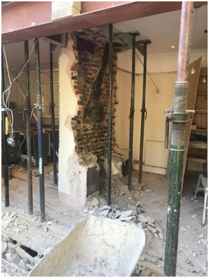
Excessive demolition and particularly the removal of roof and slab diaphragm elements without appropriate temporary shoring, can destabilize sections of existing structures.
Note: Structural instability is a threat to life and must be address immediately.
Key signs of structural instability due to demolition include:
- Rapidly Expanding Cracks
- Diagonal Cracks in Concrete Beams
- Diagonal Cracks in Concrete Walls
- Stair-step cracking in Masonry Walls
- Widening vertical tension cracks in load-bearing elements
- Severe Horizontal Cracking and Bulging in Masonry
- Walls Cracks Radiating from Corners of Windows and Doors
- Crushed or Spalling Concrete around Compressed Zones
Key signs of roof or slab discontinuity due to demolition include:
- Sagging Rooflines near Cut Zones
- Dipping RoofRidges near Cut Zones
- Rafter Separation from Supporting Walls
- Truss Separation from Supporting Walls
- Buckled Metal Deck Panels
- Sheared Fasteners
- Torn Flashing at Transition Joints
- SevereDiagonal Concrete Cracking in Slabs
- Spalling or Chipping of Concrete
- Rusting steel reinforcement
Concrete - Slab Efflorescence on the Slab Underside
- Rust Stains bleeding through Concrete Pores
Consult Preeminent Solutions’ Free Online Education Center for resources and checklists regarding structural performance:
Link: https://psengrinc.com/learning/
Contact a qualified structural engineer if your structure displays any of the above signs of structural instability.
Seismic Joint and Pounding Risk
Earthquakes impart tremendous loads unto the members, foundations, connections, and joints of building structures. As a consequence, poor seismic design and retrofit pose an imminent threat to life and public safety.
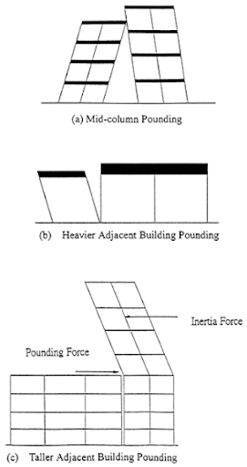
Note: Seismic joints include intentional-designed gaps between distinct sections of the same structure that allow the different parts to move independently during an earthquake. One of the purposes of a seismic joint is to prevent structural pounding and/or major structural damage.
Per the 2024 International Building Code (IBC) Code and ASCE 7-22, the governing codes on the matter at time of this publication, in seismic-prone regions, engineers shall design seismic jointsto allow for the minimum design earthquake displacements
in accordance with the code.
Key signs of inadequate seismic joint spacing risk and seismic pounding risk include:
- Narrow or Minimal Gap Between Adjacent Wings of Structure
- Misaligned Adjacent Floor Diaphragms (i.e. Diaphragms sitting at different heights, thus the slabs of one structure impact the columns of the other)
- Exaggerated Discrepancy in Adjacent Structures’ Height and Design (i.e. Tall, Slender juxtaposed to short, stout structures.)
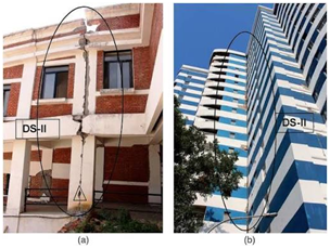
Key signs of inadequate seismic joint spacing and seismic pounding
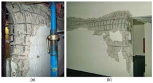
- Fracturing or Crushing of Concrete at the corners of floor slabs and/or beam edges at the corners facing the seismic joint
- SevereDiagonal CrackinginExterior Columns at the corners facing the seismic joint
- Chipping, or crushing Concrete Masonry Units (CMUs) or Brick at the corners facing the seismic joint
Consult Preeminent Solutions’ Free Online Education Center for resources and checklists regarding seismic damage:
Link: https://psengrinc.com/learning/
Contact a qualified structural engineer if your structure displays any of the above signs of seismic pounding
5Wind-Load Resistance
Often SAPF new-builds and/or pre-existing structures are situated in areas with high wind-risk, due to Hurricanes, Tropical cyclones, and/or other windstorms.
In high wind-risk regions, SAPFs must maintain robust perimeters (i.e. perimeter walls, roofs, etc.)
Per the 2024 International Building Code (IBC) Code, the governing code on the matter at time of this publication, in high wind-risk regions, structures shall be designed to withstand the minimum wind loads in accordance with ASCE 7.
Key exceptions include:
- Designs using theTelecommunications Industry Association (TIA), “Maintenance and Condition Assessment of Telecommunication Towers”, TIA-222 for antenna-supporting structures and antennas
- Wind tunnel tests in accordance with ASCE 49, “Wind Tunnel Testing for Buildings and Other Structures”
- Temporary structures in compliance with IBC Section 3013
- Designs using theNational Association of Architectural Metal Manufacturers (NAAMM) “Guide Specifications For Design of Metal Flagpoles,” NAAMM FP 1001
Key signs of high wind-risk susceptibility (i.e. poor wind-risk resistance) in buildings include:
- Missing or Under-designed Hurricane Strap Connections
- Long and/or Unbraced Overhang Eaves
- Loose and/or Degraded Roof Decking
- Loose and/or Degraded Exterior Wall Panels
- Corroded / Deteriorated Connection Fasteners
- Corroded / Deteriorated Anchorage to Foundation
- Unreinforced or Under-reinforced Masonry Walls
- Excessively Large Shear Wall Openings
- PoorFloor Slab / Roof Continuity
- Discontinuous Vertical and Lateral Load Paths
- Preexisting Failed Connection Joints at Corners
- Sagging Roof Lines
- Bowing and/or Leaning Columns and Walls (particularly at corners of structure.)
- Severe Diagonal Cracking in Reinforced ConcreteElements
- Severe Horizontal Cracking in Vertical Masonry Elements
Wind loads include major forces that impact the Lateral Force Resisting System (LFRS) , and thus the overall stability, of a structure.
It is imperative for public safety that structures are able to withstand design wind load demands, particularly in high wind-risk areas.
Key signs of wind damage in buildings include:
- Membrane peeling or unzipping along perimeter flashing and eaves.
- Twisting of Roof Purlins due to Unbalanced Wind Loads
- Buckling of Long-Span Open-web Steel Joists
- Excessive Deflection/Ponding on Roof
- Warping of Wall Panels
- Out-of-Square Roll-up Door Frames
- Out-of-plumb Columns or Portal Frames
- Deformed Anchor Bolt and Base plate Connections for Column Supports
- Fractured Welds
- Fracture Surface Corrosion due to Impact and Removal of Protective Coating
- Beam Connection Corrosion and Deterioration
Such issues are especially relevant in the retrofit of existing structures that were not originally designed to be used as a SAPF facility.
Consult Preeminent Solutions’ Free Online Education Center for resources and checklists regarding structural winddamage:
Link: https://psengrinc.com/learning/
Contact a qualified structural engineer if your structure displays any of the above signs of wind damage.
Preeminent Solutions is a DBE-certified, MWBE-certified, LDB-certified and soon to be 8(a)-certified and WOSB-certified, civil/structural engineering firm.
We have over 30 years’ experience in civil/structural design, forensics, and expert work
We’re Licensed in CA, FL, TX, NJ, NY, DC, MD, VA, TN, MS, GA, NC, SC, LA, & more.
Reach out if your team is in need of structural engineering support.
Preeminent Solutions, Inc.
Forensic Structural Engineers & Consultants
📞 (321) 244-8699 | (407) 901-0133
✉️ info@psengrinc.com
🌐 www.psengrinc.com
Author
-
Vanessa Malone, P.E. is the Owner of Preeminent Solutions, Inc.
She is a licensed civil / structural engineer with almost 15 years’ experience in civil/structural design, forensics, and expert work.
She is licensed in Florida, California, Texas, Washington D.C., Virginia, Maryland, New York, New Jersey, Louisiana, Georgia, Mississippi, North Carolina Tennessee, and several other states and territories.
She has worked with Thornton Tomasetti, Westinghouse, NASA, NOAA, the Navy, Southern Nuclear, General Electric, Bechtel, and other companies.
Malone is a first generation American. She first emigrated to the continental United States almost 20 years ago.
Malone shares her love of engineering through her company and through her interactions with other firms.
Thank you and we look forward to serving you!