Forensic Case 7: Commercial Building Temporary Support System Column Shoring
Forensic Case 7: Commercial Building Temporary Support System Column Shoring
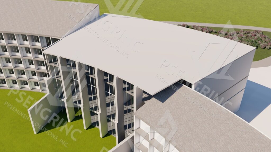
A RESORT AND SPA HOTEL
Preeminent Solutions, Inc. is pleased to offer this civil-structural engineering report. This case study documents the engineering evaluation, design, and implementation of a temporary shoring and permanent column replacement system for a commercial building located at. The project, titled “Commercial Building Temporary Support System – Column Shoring DEC,” was undertaken to address structural deficiencies identified in an existing steel column supporting a high-bay commercial structure with an approximate clear height of 32 feet.
The project was initiated after the contract identified significant damage and deformation in an existing HSS 7×7 steel column, rendering it unsuitable for continued service under commercial loading conditions. Preeminent Solutions, Inc., led by Vanessa Malone, P.E., was retained to design a safe and code-compliant temporary shoring system to support the structure during column removal, as well as to provide the design of a permanent replacement column.
During the engineering assessment, it was further determined that the existing column configuration was not adequately designed for the applied loads, independent of the observed damage. As a result, the scope of work expanded beyond replacement-in-kind to include structural re evaluation of the column system. Based on load demands, stability requirements, and current code provisions, upgraded column sections were recommended. These included HSS 10×10 and HSS 8×8 members at designated locations, as detailed in the structural drawings.
The final design incorporated a robust temporary shoring frame, engineered to safely transfer gravity and lateral loads to the foundation while maintaining roof and framing stability throughout construction. The system was designed in accordance with the 2023 Florida Building Code (8th
Edition) and applicable ASCE 7 load provisions, ensuring structural integrity, worker safety, and uninterrupted building performance during column replacement activities.
This project highlights the importance of field verification, structural assessment of existing conditions, and engineered temporary works when modifying critical load-bearing elements in commercial structures. The successful execution of the shoring and replacement strategy provided a safe transition from deficient existing conditions to a permanent, code-compliant structural solution.
Project Description:
Scope of Services:
The project scope includes engineering services associated with the temporary support of the building structure during removal and replacement of an existing damaged steel column. The existing column, identified as an HSS 7×7 member, exhibited deformation and was determined to be unsuitable for continued service in a commercial structure with an approximate 32-foot clear height. Preeminent Solutions, Inc. was retained to design a safe and code-compliant temporary shoring system to maintain structural stability throughout construction, as well as to provide the design of the replacement column system.
Specifically, Preeminent Solutions, Inc. has been engaged to provide the following:
a) An Engineering Report that notes:
- Observed and reported deficiencies in the existing structure, including findings from:
- The forensic site inspection of the subject structure
- Key files provided by the Client
- Structural Analysis of the subject structure, including a Finite Element
Analysis (FEA) of the structure used to perform a sensitivity analysis of the structure under progressively increasing load.
- Recommendations to mitigate noted structural deficiencies.
The scope of structural engineering services include:
a) An Engineering Report that includes findings from:
i. The forensic site inspection of the subject structure
ii. Key files provided by the Client
iii. Structural Analysis of the subject structure, including a Finite Element Analysis (FEA) of the structure used to perform a sensitivity under progressively increasing load.
Note: FEA analysis and the site inspection were performed by the inspecting engineer. The inspecting engineer has over 10 years’ experience in FEA analysis of structures ranging from nuclear powerplants to aeronautical structures owned and operated by NASA.
Deliverables:
As requested, we:
a) Performed visual observations of the areas of interest/concern.
b) Provided a verbal report of our findings.
b) Prepared an Engineering Report that includes:
i. Summary of the findings of site inspection and model
ii. Recommendations to mitigate structural deficiencies.
File Materials Reviewed
In preparation for the report and analysis, the engineer reviewed the documents noted below:
a) Files provided by Client pertaining to the subject structure and loss
b) Federal Emergency Management Agency (FEMA) Flood Hazard Data for the subject structure
c) ASCE Hazard Data for the subject structure
d) U.S. Geological Services (USGS) Site Data
e) National Oceanic and Atmospheric Administration (NOAA) National Centers for Environmental Information (NCEI) for Date of Loss
f) Photographs taken at site walkdown by inspecting engineer
Documents Cited:
N/A
Structural Description:
The project consists of the structural evaluation, temporary support (shoring) design, andvpermanent column replacement for an existing one-story commercial building located at 3342 Crawfordville Highway, Crawfordville, Florida. The building has an approximate interior floor area of 5,007 square feet and is situated on a 1.72-acre parcel. The structure is currently configured as a multi-tenant commercial facility accommodating retail and office occupancies.
Existing Structural System
The building’s vertical load-resisting system includes steel hollow structural section (HSS) columns supporting roof framing elements and transferring gravity loads to the foundation system. The structure has an approximate overall height of 32 feet, resulting in significant axial demand on the column members.
One of the primary columns within the building was identified as an HSS 7×7 steel member exhibiting visible deformation and damage. The observed distortions compromised the structural integrity and load-carrying capacity of the column, rendering it unsuitable for continued service under current loading conditions. Further review revealed that the existing column system appeared to be undersized and lacked verifiable engineering design documentation, raising concerns regarding overall structural adequacy.
Engineering Evaluation and Scope of Work
Preeminent Solutions, Inc. was retained by the contractor to perform a structural assessment
and provide engineering design services for:
- Temporary shoring to safely support the structure during column removal and replacement
- Design of replacement steel columns meeting current structural demands
- Recommendations for upgrading additional existing columns determined to be structurally inadequate
Structural Description – Temporary Shoring System
For the purpose of this report only the temporary shoring, the columns, and the roof of the subject structure were inspected.
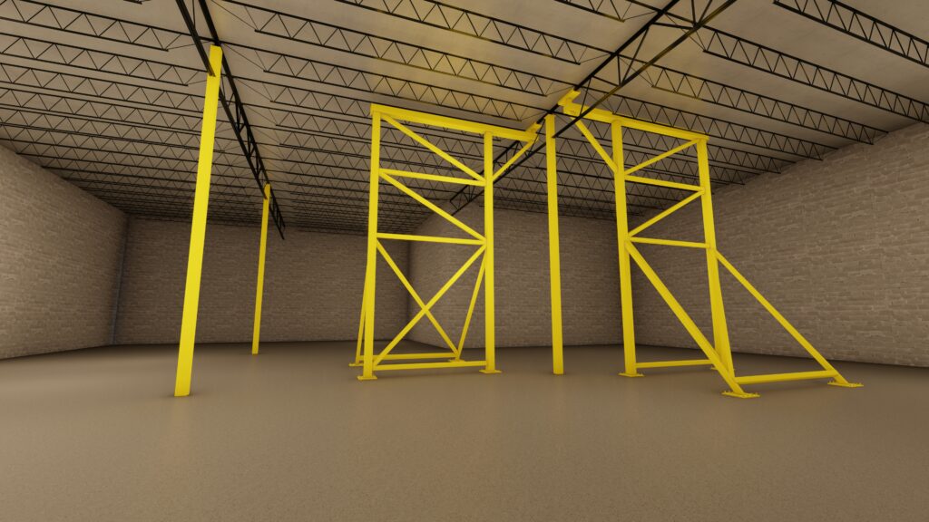
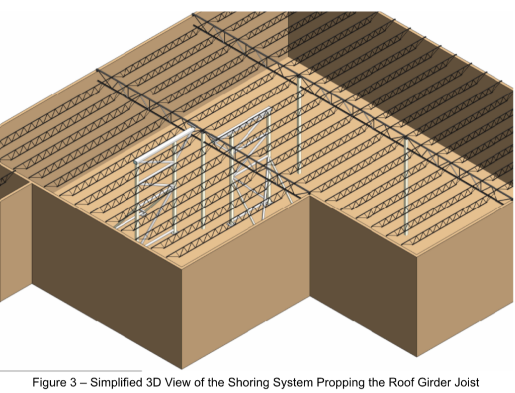
The temporary shoring system consists of a free-standing, braced steel frame designed to support the existing roof and superstructure during removal and replacement of the damaged column. Two identical shoring frames are utilized, installed symmetrically on both sides of the column, each located approximately 2 feet from the column centerline.
One shoring frame is oriented facing north, and the second frame is oriented facing south, providing balanced load transfer and lateral stability in both principal directions.
The shoring systems are temporary in nature and will be removed only after the permanent replacement column is fully installed and capable of supporting all applied loads.
See Image below for figure detail:
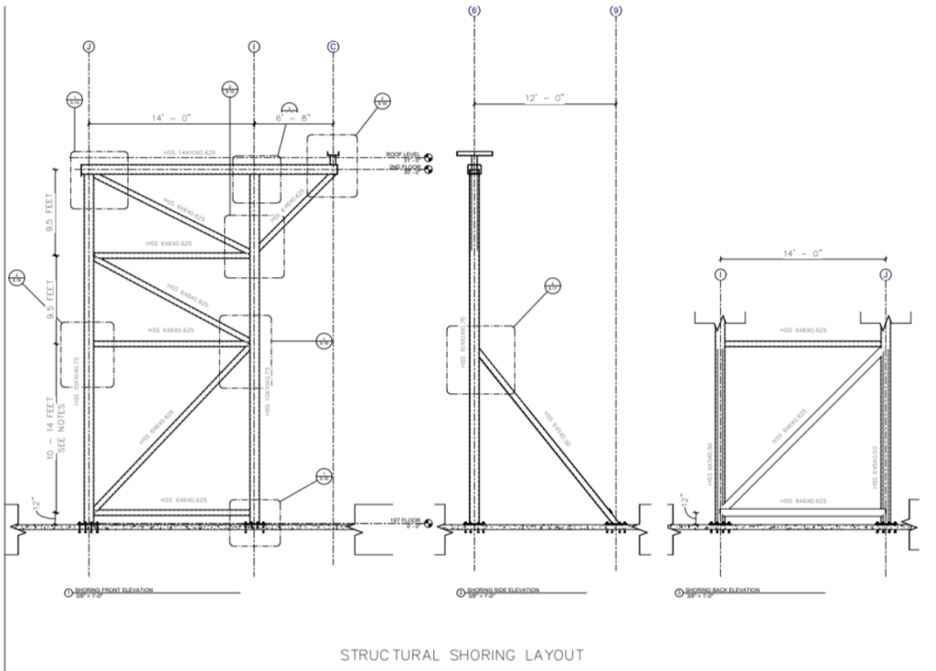
Each shoring frame extends from the slab-on-grade to the roof framing level and is composed of HSS 10×10×0.75 vertical columns supporting a roof-level HSS 14×10×0.625 transfer beam. The transfer beam receives gravity loads from the existing roof framing and distributes them into the
shoring columns.
Intermediate framing consists of HSS 6×6×0.625 horizontal members provided at multiple elevations to reduce unbraced lengths of the vertical members and improve overall stiffness. HSS 6×6×0.625 diagonal bracing members are installed in a triangulated configuration in the front, side, and back elevations to resist lateral loads, control buckling, and stabilize the system during construction.
Shoring columns bear on the existing slab-on-grade through steel base plates designed to transfer axial loads without overstressing the slab. All members act together as a three- dimensional braced frame capable of resisting gravity and construction-induced lateral forces.
The shoring frames are temporary and will remain in place until the permanent replacement columns are fully installed, connected, and capable of independently supporting all applied loads, after which the shoring will be removed in a controlled sequence.
Structural Description – Roof System
For the purpose of this report only the roof, columns, and beams of the subject structure were inspected.
Roof appears to be built up roof consisting of elements including insulation, decking, and roofing membrane.
Roof composition is not known at the time of this report. Further inspection, testing, and/or review of original structural drawings and as-built structural drawings is required to ascertain this data.
Potential Future Load
If the damaged and undersized existing column were left in place, the building would remain at risk of progressive structural deterioration and potential failure. The observed deformation indicates that the column has likely experienced overstress, reducing its effective cross-
sectional capacity and increasing susceptibility to instability.
Given the building height and axial loading demands, continued service of the original column could result in local buckling, global column instability, or excessive axial shortening, particularly under increased roof loads, wind loading, or accidental load eccentricities. Any further loss of
section capacity or alignment could compromise the load path, leading to overstressing of adjacent structural members.
Render of proposed shoring system with the column and the roof are detailed below.
Additionally, the lack of verified engineering design for the existing column system suggests that reserve capacity is minimal. Over time, this condition could contribute to progressive load redistribution, resulting in distress to roof framing connections or adjacent columns. In extreme cases, localized column failure could lead to partial roof collapse or disproportionate structural damage.
The column replacement and associated upgrades mitigate these risks by restoring adequate axial strength, stiffness, and stability, thereby reducing the likelihood of future structural failure and extending the service life of the building.
Column Failure
The existing column exhibited visible deformation and was determined to be undersized for the applied axial loads associated with the building height and roof system. Continued service of this column would significantly increase the risk of local wall buckling, overall column instability, or axial capacity failure, particularly under sustained gravity loads combined with wind-induced forces.
Column deformation introduces load eccentricity, which amplifies bending stresses and accelerates loss of capacity. Over time, this condition could result in progressive worsening of the column alignment and stiffness, increasing the likelihood of sudden or brittle failure. Failure of the column would disrupt the primary vertical load path and force load redistribution to adjacent structural members that may not be designed to accommodate the additional demand.
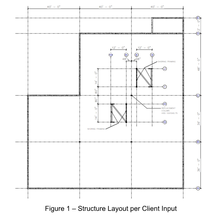
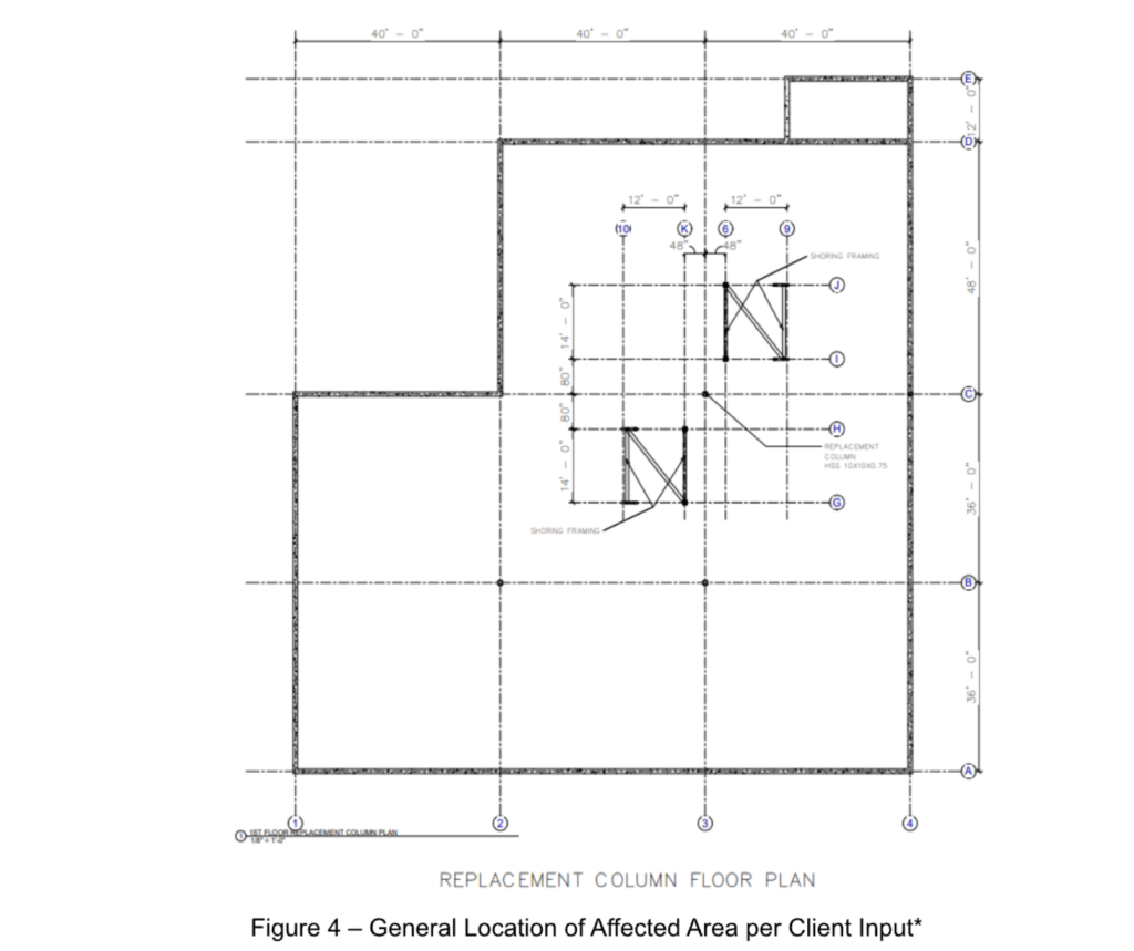
Affected Area
The affected area is localized around the interior steel column identified for replacement and the structural elements directly supported by it. This includes the immediate roof framing tributary to the column, adjacent roof beams or girders, and the portion of the slab-on-grade at the column base.
Due to the observed deformation and inadequate capacity of the existing column, the roof framing in this area was subject to increased deflections and stress concentrations. Any reduction in column stiffness or alignment adversely impacts the supported roof members, potentially causing overstressing of beam-to-column connections and localized roof system distress.
Adjacent columns and framing members within the same structural bay may also be indirectly affected through load redistribution. In the event of further column deterioration, gravity loads would be transferred to nearby structural elements not designed to carry the additional demand,
increasing the risk of secondary structural damage.
The affected area also includes the immediate floor area surrounding the column, where
bearing pressures at the slab interface could increase under compromised load transfer. While the issue is localized, the consequences of failure could extend beyond the immediate bay and result in partial roof instability within the interior portion of the building.
The column replacement and temporary shoring were therefore limited to this defined area to stabilize the structure, protect adjacent framing, and prevent progression of structural distress.
Details for the Affected Area are shown below.
Loads and Load Path
Consult Appendix O.
Observations – General Overview
Observations include site inspection observations, document review, and structural analysis. Details per section are listed below.
Observations – Structural Analysis - General Overview
Observations – Structural Analysis - General Overview – FEA Analysis and P-Delta Effects
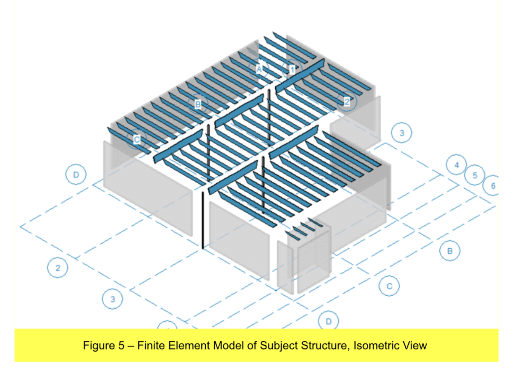
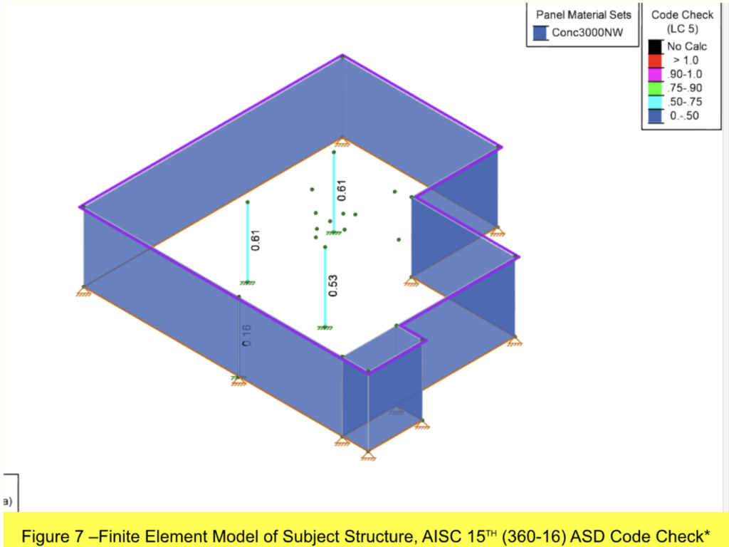
Finite Element Analysis (FEA) was used to evaluate columns and girder beams. Finite Element Analysis is a computational method used to analyze how a physical structure or system behaves under different loads in accordance with the laws of physics. Finite Element Analysis is commonly used in the analysis of complex structures including buildings and structural components under indeterminate loads. FEA analysis was also used to determine reaction loads for joists.
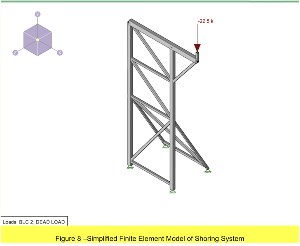
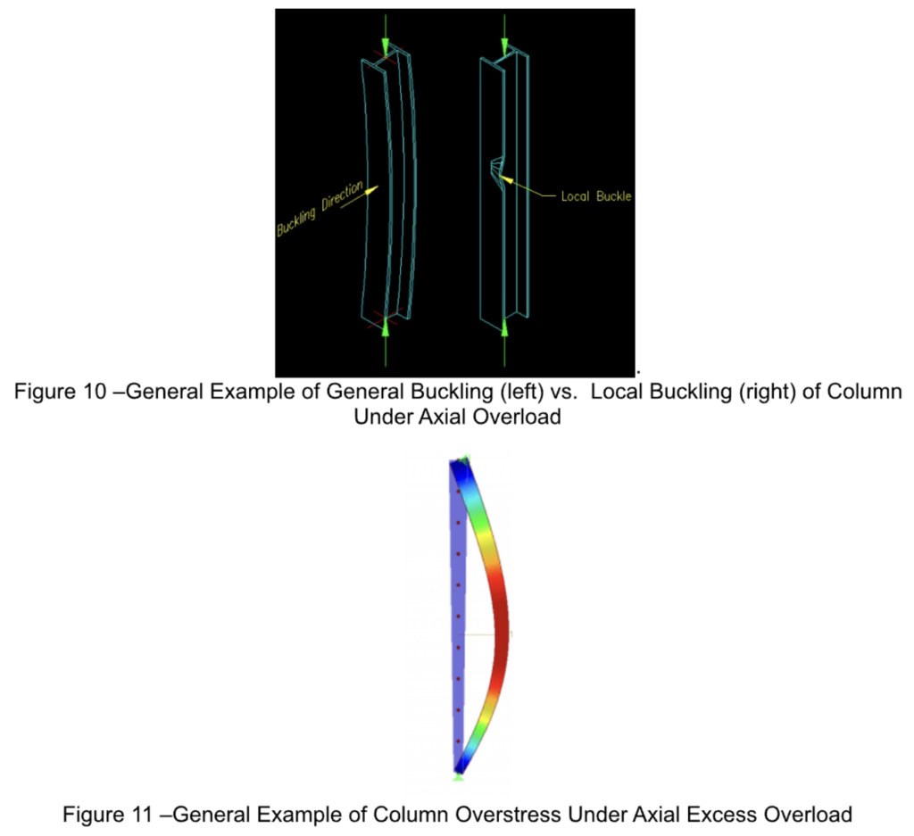
FEA analysis allowing for P-Delta effects was used to evaluate columns and girder beams. P-Delta analysis is a phenomenon in structural engineering in which the interaction between axial loads and lateral displacement results in increased forces and moments experienced by the member. This effect commonly occurs in columns overloaded in the axial direction, resulting in general buckling. An example of general buckling is provided the figures below. FEA analysis assuming linear elastic analysis (no P-Delta effects) was utilized determine reaction loads for joists.
See structural model below:
Observations – Structural Analysis - Methodology
Observations – Structural Analysis - Methodology
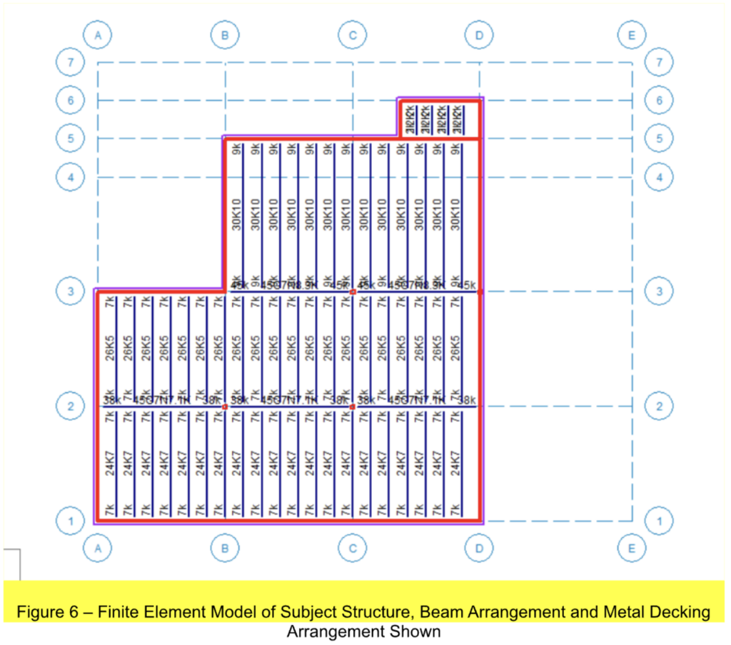
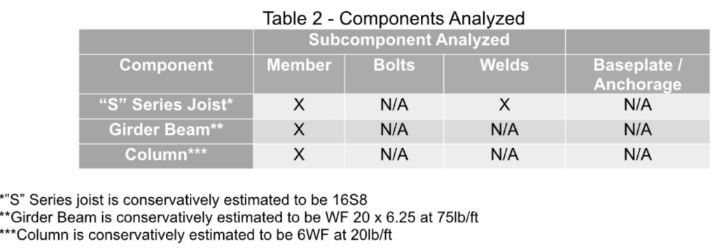
Based on on-site measurements and codes, column members, girder members, and joist members are conservatively estimated to be HSS 7X7X0.625, 44G7N9.34K; and 30K10, respectively.
A structural analysis was performed to evaluate the adequacy of the existing column and to develop a safe temporary shoring and permanent replacement solution. The methodology included a review of available construction drawings, site observations, and visual inspection of the existing structural components.
The analysis considered gravity loads from the roof system, self-weight of structural members, and applicable construction loads. Member sizes, unbraced lengths, and column slenderness were evaluated using accepted structural engineering principles and current design standards.
Due to the absence of verified original design calculations, conservative assumptions were applied to ensure safety.
Load paths were identified to assess how forces are transferred from the roof framing to the columns and into the slab-on-grade. Temporary load redistribution during construction was also analyzed to ensure that the shoring systems could safely support the structure during column removal and replacement.
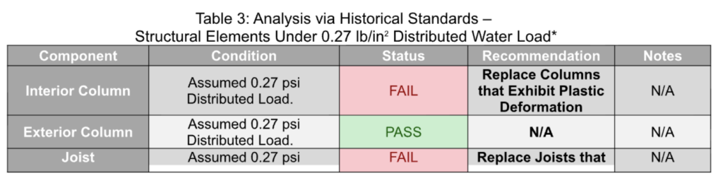
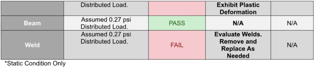
See the table below for further details:
See Appendices N, O, P, Q, R, S, and T for further details.
Observations – Structural Analysis - Methodology
Components and connections were analyzed for static, not dynamic, loading
The structural analysis confirms that the replacement column, designed as HSS 10×10×3/4, provides adequate axial strength, stiffness, and serviceability for the building’s height and applied roof loads. The existing HSS 7×7×1/4 column was severely undersized and exhibited visible deformations, confirming that it was structurally inadequate for continued service. While a temporary upgrade to HSS 7×7×3/4 could improve capacity during construction, it would not meet long-term performance requirements.
The replacement HSS 10×10×3/4 column restores a safe vertical load path and ensures proper load transfer from the roof framing to the slab-on-grade. It also eliminates the risk of excessive deflection, local or global buckling, and potential progressive failure in the roof system. Analysis
indicates that the column will perform well under gravity and wind loads, providing the required structural reliability and compliance with design standards.
Temporary shoring systems were verified to safely support the building during column removal and installation, maintaining stability independent of the existing column. Once the replacement column is installed and verified, the temporary shoring can be safely removed without risk to the
structure.
In summary, the analysis demonstrates that the HSS 10×10×3/4 replacement column is fully capable of meeting current load demands, restoring the integrity of the affected area, and mitigating all identified structural deficiencies.
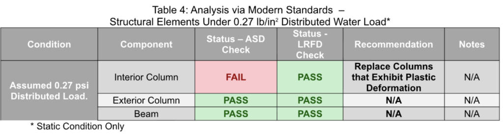
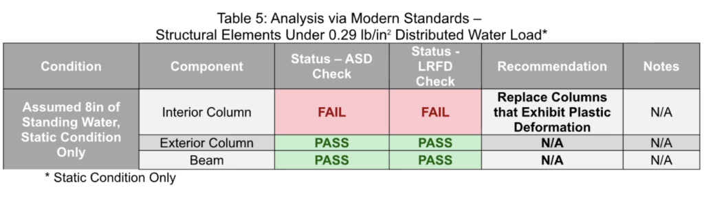
Likewise, see the figures and tables below for further details:
Limitations and Supplemental Findings
While conservative assumptions were made based on available building information, there are multiple unknowns with the subject structure. Further inspection, testing, and/or review of original structural drawings and as-built structural drawings is required to attain pertinent data to more accurately determine structural design intent.
Similarly, the FEA model contains data supporting additional conclusions relevant to the report. Preeminent Solutions intends to supplement the document with this data at a later time.
Recommendations
There are multiple unknowns with the subject structure.
Based on the observed condition of the existing column, structural evaluation, and analysis of the building’s load-resisting system, the following recommendations are provided:
A. Immediate Structural Support
Maintain the temporary shoring systems in place until the replacement column is fully installed, properly connected, and verified to be carrying the required structural loads. No removal of shoring should occur prior to engineer approval.
B. Column Replacement
Remove the existing damaged and undersized column and replace it with the designed HSS 10×10×0.75 steel column at the location shown on the construction drawings. Installation shall be performed plumb and aligned with the existing structural grid.
C. Connection and Base Support
Install all column base plates, anchorages, and roof framing connections in accordance with the engineered details. Ensure full bearing at the slab-on-grade and proper load transfer into the supporting elements.
D. Construction Sequencing
Follow the specified construction sequence to prevent unintended load redistribution. Loads shall be gradually transferred from the shoring system to the replacement column after installation and inspection.
E. Inspection and Verification
Perform field verification of member sizes, alignment, and connections prior to removal of temporary shoring. Any deviations from the design documents shall be reviewed by the structural engineer of record.
F. Future Structural Performance
Implement the recommended column upgrades indicated in the drawings, including the use of larger HSS sections where noted, to ensure uniform load distribution and long-term structural reliability.
G. Maintenance and Monitoring
Periodically inspect the replaced column and adjacent structural components for signs of distress, corrosion, or movement, particularly following significant loading events.
Implementation of these recommendations will restore the integrity of the building’s vertical load-resisting system, reduce the risk of future structural failure, and ensure safe long-term performance of the structure.