A Warehouse Forensic Case Study
Introduction
A Warehouse Forensic Case
Preeminent Solutions, Inc. is pleased to offer this civil-structural engineering report regarding the assessment, evaluation, and analysis of Warehouse 1 of the existing structure.

Background Information
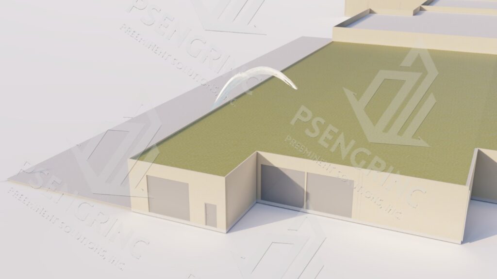
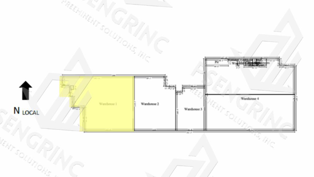
Warehouse 1 (i.e. the subject structure) is a single story warehouse.
For the purpose of the study, all directions are given from the perspective of an individual facing the local north direction of this structure. The subject structure is the first of four warehouses connected axially in the local east to west direction. The subject structure is roughly 24,000 sq-ft with primarily concrete block exterior walls and reinforced concrete foundation.
The Client has estimated the structure to have been constructed in the 1960s.
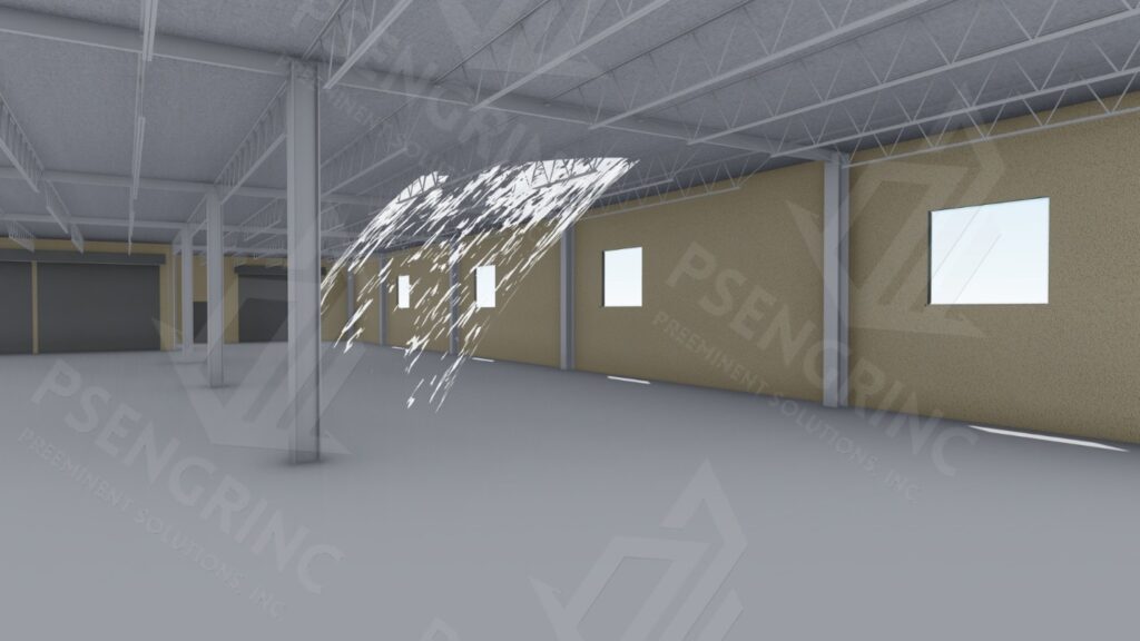
The subject structure has interior steel columns regularly spaced roughly 30 ft on-center in both the local north-south and the local east-west directions. The subject structure has interior steel girder beams that span roughly 30 ft from column to column in the local north-south direction.
Lastly, the subject structure has steel joists that span roughly 30 ft and run in the local east-west direction.
Columns and walls of the subject structure were measured to be roughly 15ft – 10in tall as measured from top of slab to bottom of roof metal decking.
The subject structure has a 10in tall parapet wall and several drainage points on the roof. The vertical load path of the subject structure flows from the roof to the joists to the girder beams, to the columns to the baseplate and anchorage, and then to the foundation.
Problem Statement / Objectives
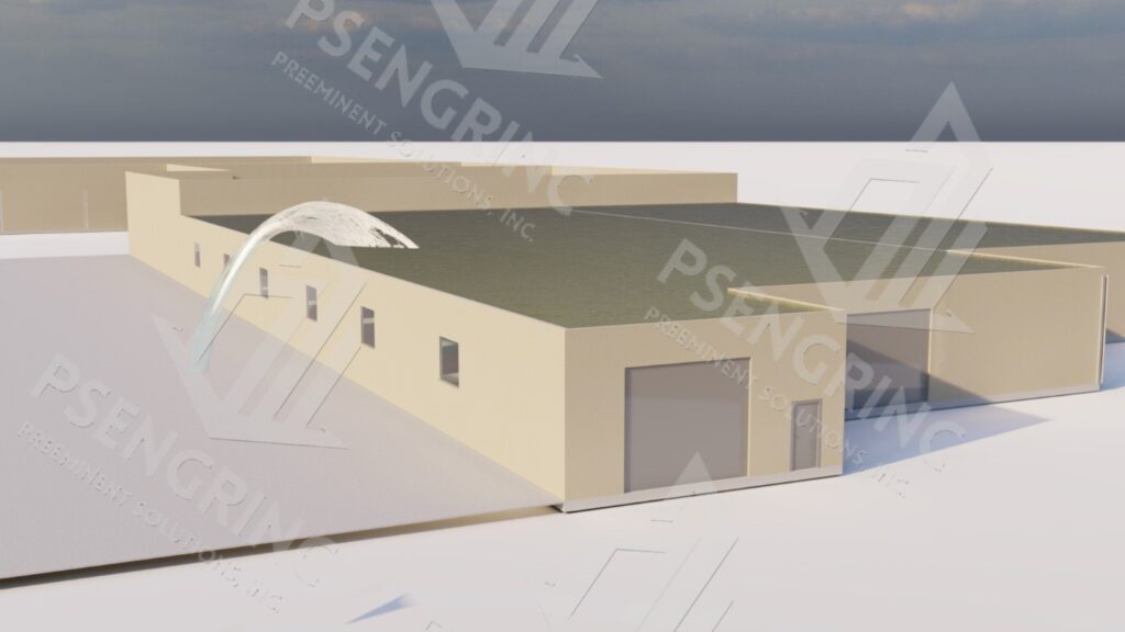
The study provides expert opinion on the reported and observed damages, potentially caused by overloading of the roof structure due to the failure of the fire suppression system and the consequent accumulation of excess water on the roof.
Note: Failure of the fire suppression system includes the rupture of the exterior pipe and the consequent failure of the structure’s fire suppression wet lines.
Based on inspection observations, the subject structure displays several key structural deficiencies namely:
- Overburdening of Joists,
- Overburdening of Columns,
- Reduction of building envelope via roof opening
Based on the aforementioned observations and engineering judgement, we believe that with a reasonable degree of engineering certainty the load on the date of loss resulted in overburdening of the joists, columns, and joist-to-girder welds of the subject structure.
Based on the aforementioned observations and engineering judgement, we believe that such overburdening resulted in plastic (i.e. permanent) deformation in the structural components.

- Structural Description – Roof Truss System
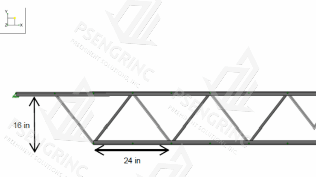
For the purpose of this study only the roof, columns, and beams of the subject structure were inspected. Roof truss (i.e. joist) system utilizes 16in-deep steel product Warren trusses, with a roughly 5ft center-to-center spacing between adjacent joists. Joists have a regular panel spacing of 24in. Panel spacing near the walls is unknown and could not be verified at the time of our visit.
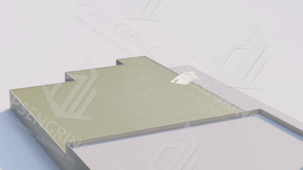
- Pipe Rupture
The report addresses effects caused by overloading of the roof structure due to the failure of the fire suppression system and the consequent accumulation of excess water on the roof.

The study addresses effects caused by overloading of the roof structure due to the failure of the fire suppression system and the consequent accumulation of excess water on the roof.
Analysis / Findings
- Site Description
Preeminent Solutions performed an initial site inspection of the structure on 16 July 2025. At the time of the site inspection the majority of collapsed joists and roof members had been removed. For the purpose of the report, all directions are given from the perspective of an individual facing due the local north direction of this structure.
Observations made during this site inspection followed, but were not limited to, recommendations described in the American Society of Civil Engineers (ASCE) Guidelines for Structural Condition Assessment of Existing Buildings, Standard SEI/ASCE 11-99. Furthermore, assessment has been conducted in accordance with several other standards including, but not limited to, ASTM E678-07, Reapproved 2013 and the 2018 International Building Code. Note: As of August 2025, the St. Louis, MO Building Code St. Louis, Missouri City Hall notes that the St. Louis Building Code adopts the 2018 International Building Code. That said, the 2018 International Building Code is a set of standards, established by the International Code Council (ICC) to ensure the safety, health, and general welfare of building occupants.
Observations
Preeminent Solutions performed structural analysis to determine the cause of failure.
Structural analysis of the columns, joists, and girder beams of the subject structure comply with historical codes applicable at the estimated time of construction, namely: the Southern Building Code (1950 revision); the American Institute of Steel Construction (AISC) Steel Construction Manual 5th edition (published 1949); the Laclede Steel Company Straight Chord Steel Joists catalog (published 1959), and the Steel Joist Institute (SJI) 75-Year Steel Joist Manual. Structural analysis of the columns and girder beams of the subject structure also comply with modern codes including the AISC Steel
Construction Manual 15th edition and ASCE Minimum Design Loads and Associated Criteria for Buildings and Other Structures, ASCE/SEI 7-22.
Finite Element Analysis (FEA) and hand calculations were used to evaluate columns, girder beams, and welds. Hand calculations were also used to evaluate historical S joists.
- FEA Analysis and P-Delta Effects
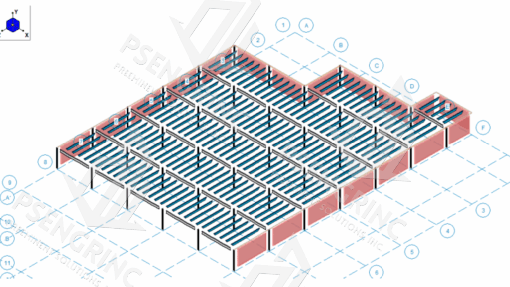

FEA analysis allowing for P-Delta effects was used to evaluate columns and girder beams. P-Delta analysis is a phenomenon in structural engineering in which the interaction between axial loads and lateral displacement results in increased forces and moments experienced by the member. This effect commonly occurs in columns overloaded in the axial direction, resulting in general buckling. An example of general buckling is provided the figures below. FEA analysis assuming linear elastic analysis (no P-Delta effects) was utilized determine reaction loads for joists.
• Results
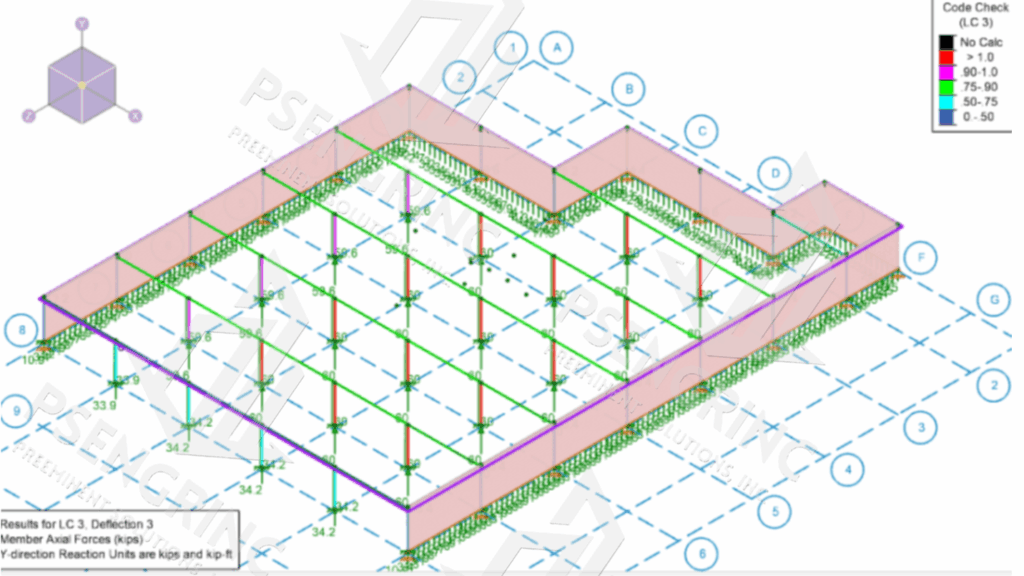
Components and connections were analyzed for static, not dynamic, loading ASD analysis results show overloading of column and “S” joists once applied distributed water loading exceeded 0.27 lb/in2 (equivalent to 7½ inches of standing water). LRFD analysis results also show overloading of column and “S” joists once applied distributed water loading exceeded 0.29 lb/in2 (equivalent to 8 inches of standing water). Overburdening of the column can result several signs of failure including local flange buckling and/or general buckling and failure of column.
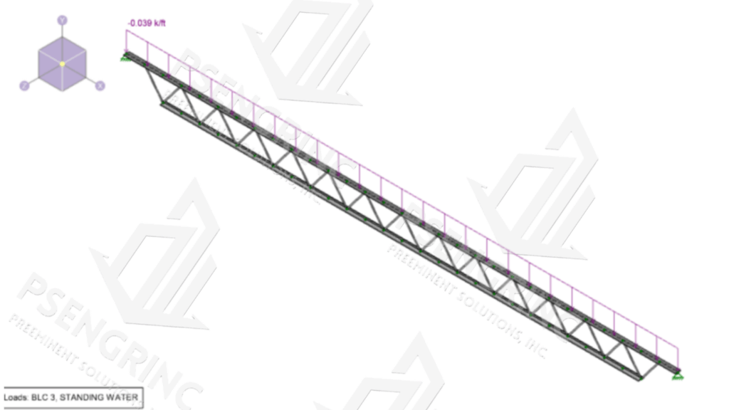
Analysis also showed overloading of the joist to beam weld under 0.27 lb/in2 distributed water load and linear elastic analysis.
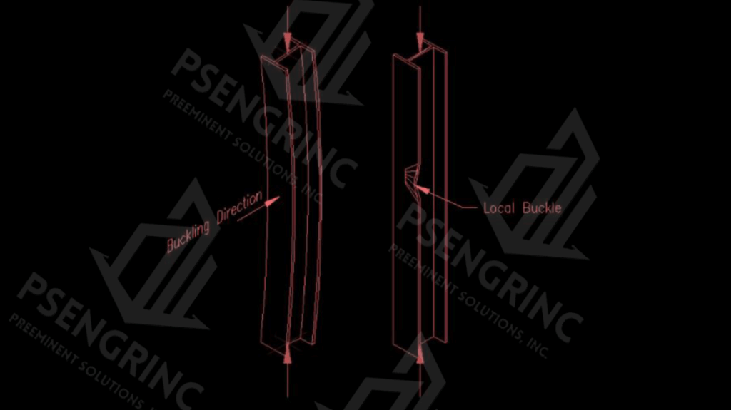
General Example of General Buckling (left) vs. Local Buckling (right) of Column Under Axial Overload
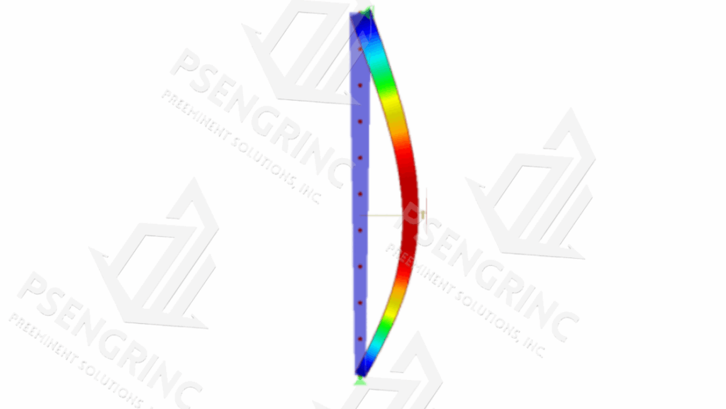
General Example of Column Overstress Under Axial Excess Overload
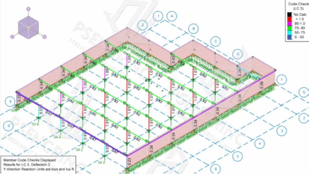
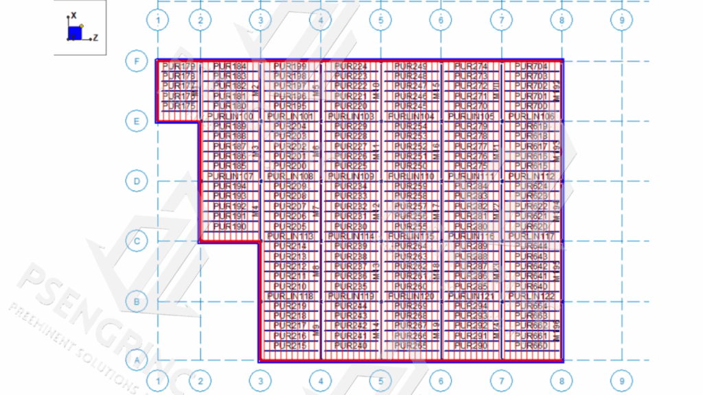
Finite Element Model of Subject Structure, Column Code Check Under 0.27 lb/in2, Distributed Water Load Service Load, 2018 IBC ASD Code Check*
Recommendations
- Roof
The following recommendations are advised to address the aforementioned deficiencies.
- a) Exposed Roofing Elements Near Affected Area
It is advised to inspect roof for moisture intrusion via follow-up site inspection and testing methods. If no detrimental conditions exist re-seal roof using appropriate construction means and methods.
- b) Minor Blistering in Built Up Roof System
Blisters may be caused by excess moisture in roof system.
- c) Ponding Water on Built Up Roof System
Ponding water exasperates the deterioration of the roof membrane and applies additional loads to the overall structure.
It is advised to address roof slope issues via the use of crickets (also called saddles) or similar device to properly route water to drainage points.
- d) General Observation: Clogged Roof Drains
Clogged drains exasperate ponding and thus additional load on roof. It is advised to regularly inspect and promptly unclog all drains and associated piping of debris or clogged items.
- e) General Observation: Potential Water Stains on Warehouse 1 and Warehouse 2 Party Wall.
Recommendation: N/A
- f) General Observation: Pieces of Asphalt on Roof, Rocks and Other Debris on Roof
It is anticipated that pieces of asphalt, rocks, and debris originated from the region of pipe failure. It is possible that projectile asphalt, rocks and debris could have damaged roof membrane upon impact.
- g) General Observation: Vegetation on Roof
Vegetation, and particularly the root systems of vegetation, can potentially damage the roof membrane.
- Roof and Roof Truss System
- a) Failed Joist in Affected Area
Failed joists no longer efficiently route lateral or vertical loads. It is advised to remove and replace failed joists.
- b) Buckled Bottom Chord on Interior Joist Adjacent to Affected Area
Joist exhibits plastic deformation indicating overloading. It is advised to remove and replace this and other similarly failed joists.
- c) Local Defect Bottom Chord in Interior Beam
Chord defect affects the ability of the joist to resist load. It is advised to repair chord defect. If repair is not possible it is advised to remove and replace joist.
- d) General Observation: Lack of Lateral Bracing
Lateral bracing is important for the strength of the overall joist system. It is advised to add lateral bracing in accordance with code minimums.
- e) Buckled Bottom Chord on Interior Joist Near Affected Area
Joist exhibits plastic deformation indicating overloading. It is advised to remove and replace this and other similarly failed joists.
- f) Sag at Joist End
Joist exhibits sag and plastic deformation indicating overloading. It is advised to remove and replace this and other similarly failed joists.
- Roof and Roof Truss System
- a) Buckled Column Flanges
Local Lateral Torsional Buckling of the column indicates excessive flexural moment, which is realistically attributable to overburdening and consequent to P-Delta effects. Such buckling reduces the ability of the column to support additional vertical and lateral load.
Due to the location of the subject structure in a seismically active area, it is strongly advised that all columns exhibiting buckling failure be removed and replaced.
Prior to removal, it is advised to shore all associated beams, joists, and roofing members that fall within the tributary area of affected columns.
- b) Deformed Column Flange
Deformed flanges affect the ability of the column to resist lateral load.
Due to the location of the subject structure in a seismically active area, it is strongly advised that all columns exhibiting deformed flanges be removed and replaced.
Prior to removal, it is advised to shore all associated beams, joists, and roofing members that fall within the tributary area of affected columns.
Conclusions
The subject structure displays several key structural deficiencies, namely:
- Overburdening of Joists,
- Overburdening of Columns,
- Reduction of building envelope via roof opening
Based on the observations, it is anticipated that the failure of the fire suppression system resulted in the accumulation of excess water on the roof, resulting in a load in excess of 0.27 psi.
Based on the aforementioned observations and engineering judgement, I believe that with a reasonable degree of engineering certainty the load on the January 20, 2024 date of loss resulted in overburdening of the joists, columns, and joist-to-girder welds of the subject structure.
Based on the aforementioned observations and engineering judgement, I believe that such overburdening resulted in plastic (i.e. permanent) deformation in the structural components.