Call us for your next project today! (407) 901-0133
Menu
Airplane Hanger Simplified Case Study
Introduction
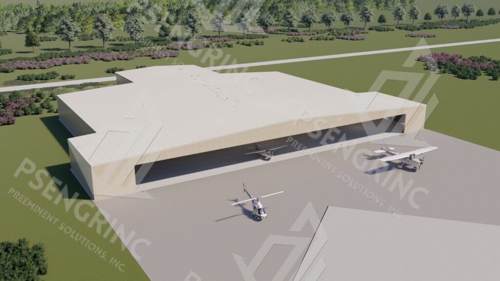
AN AIRLINE HANGAR
Preeminent Solutions, Inc. is pleased to provide this forensic civil-structural engineering report to regarding the assessment, evaluation, and analysis of the fire suppression system upgrades for the Airline Hangar.
Problem Statement / Objectives
The objective of this report is to evaluate the structural implications of proposed upgrades to the fire protection system at the Airline Hangar. The project involves the installation of additional fire suppression piping alongside the existing system, requiring analysis of the combined loads from both the new and existing piping networks. This report examines the resulting effects on the roof structure, verifies the adequacy of the current framing to sustain the increased load demands, and identifies potential risks of overloading or structural failure. Based on this assessment, the report further provides design recommendations for feasible structural modifications or reinforcements to ensure continued compliance with applicable NFPA fire protection standards and building code requirements while maintaining the structural integrity and safety of the hangar facility.
Specifically, Preeminent Solutions, Inc. has been engaged to provide the following:
An Engineering Report that notes:
Observed and reported deficiencies in the existing structure, including findings from:
The forensic site inspection of the subject structure
Key files provided by the Client
Structural Analysis of the subject structure, including a Finite Element Analysis (FEA) of the structure used to perform a sensitivity analysis of the structure under progressively increasing load.
Recommendations to mitigate noted structural deficiencies.
Analysis / Findings
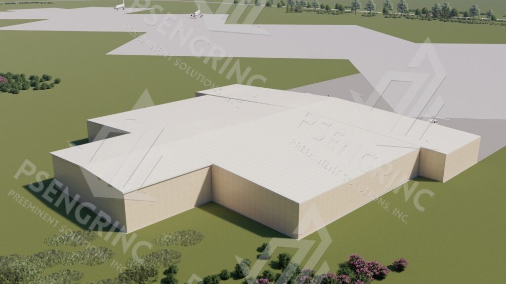
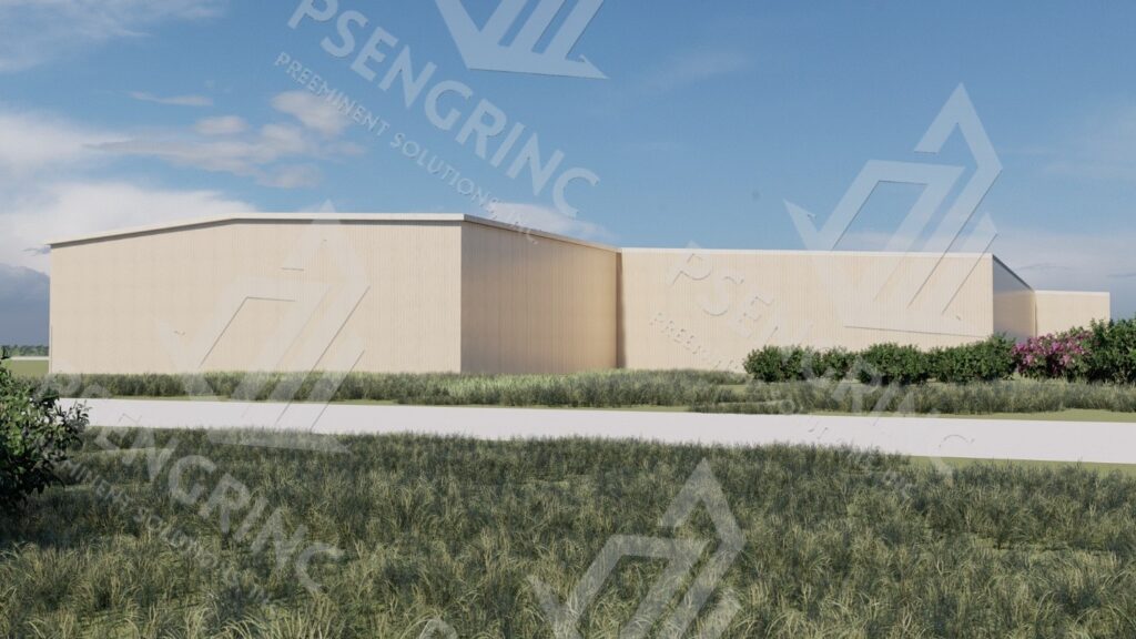
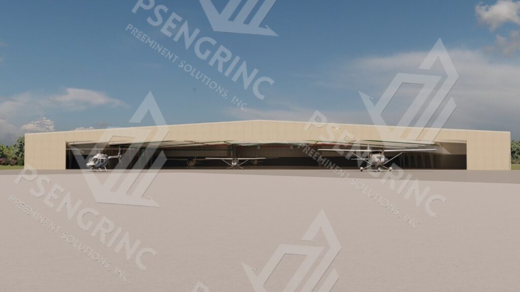
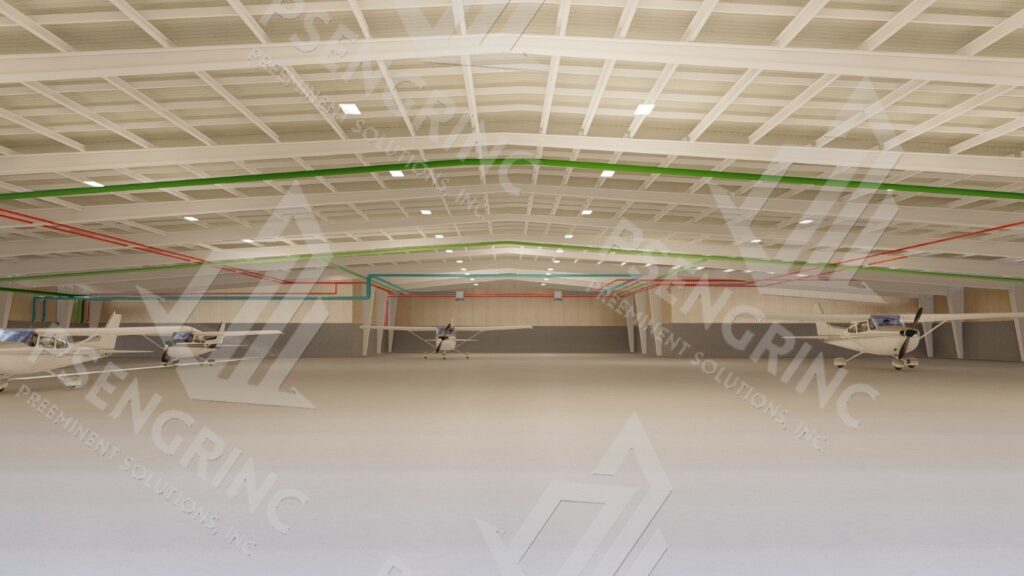
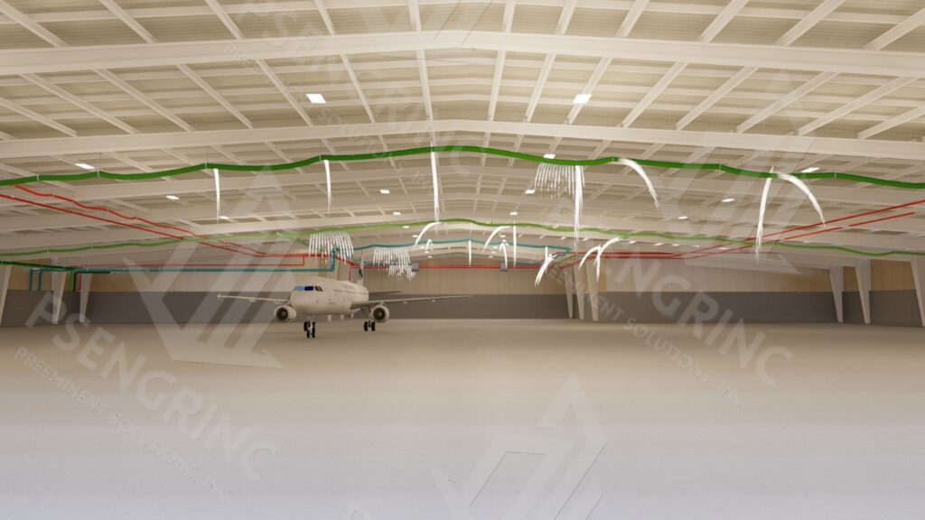
The subject structure is the Airline Hangar, a steel portal-frame aircraft hangar. The facility, constructed in the 1980s, is a historic single-bay hangar with an approximate footprint of 60,000 square feet and a total height of 81 feet, providing a clear interior height of approximately 40 feet.
For the purposes of this report, all directions are given relative to true north, which aligns with the building’s orientation.
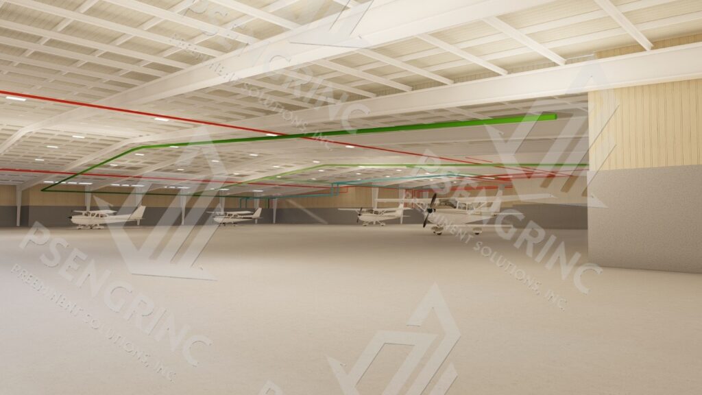
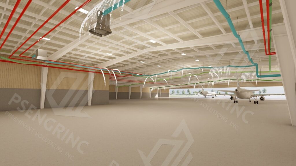
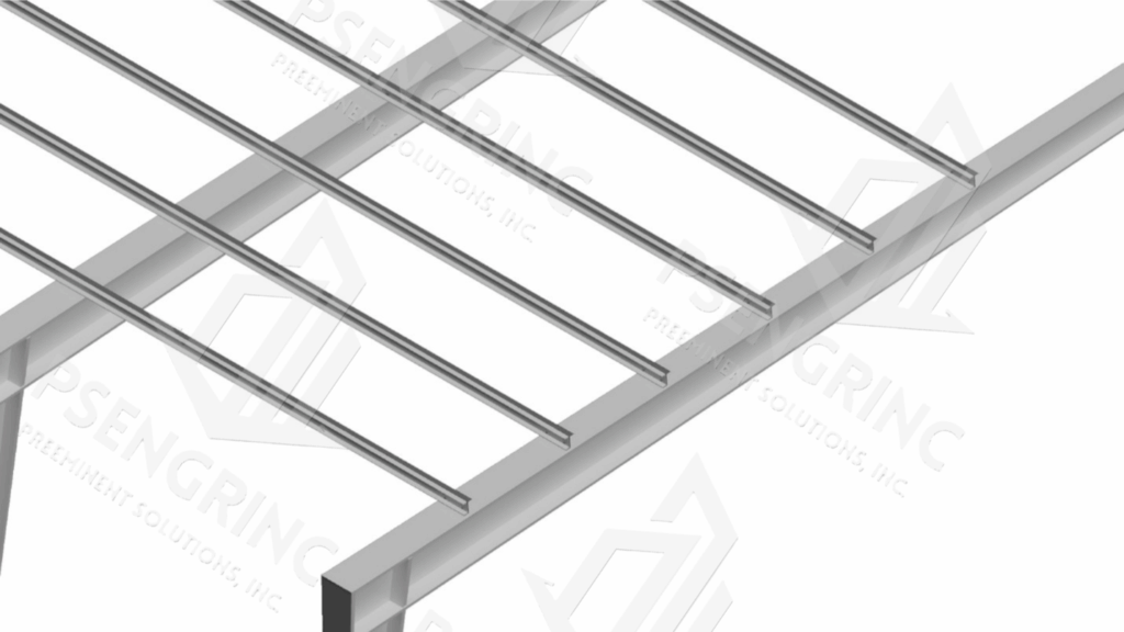
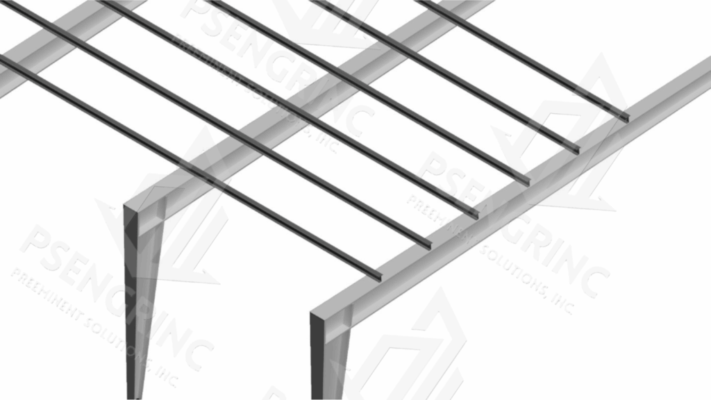
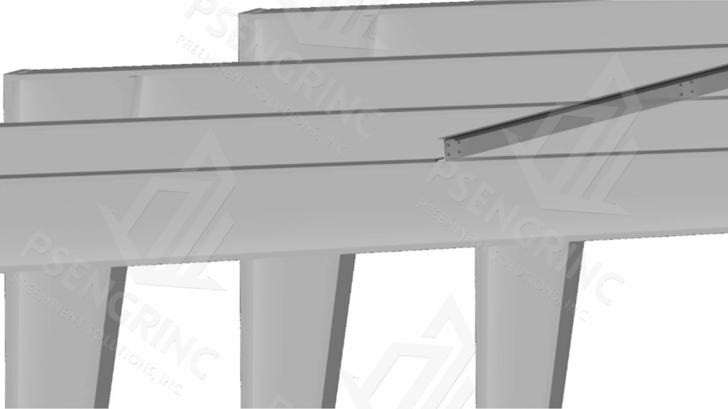
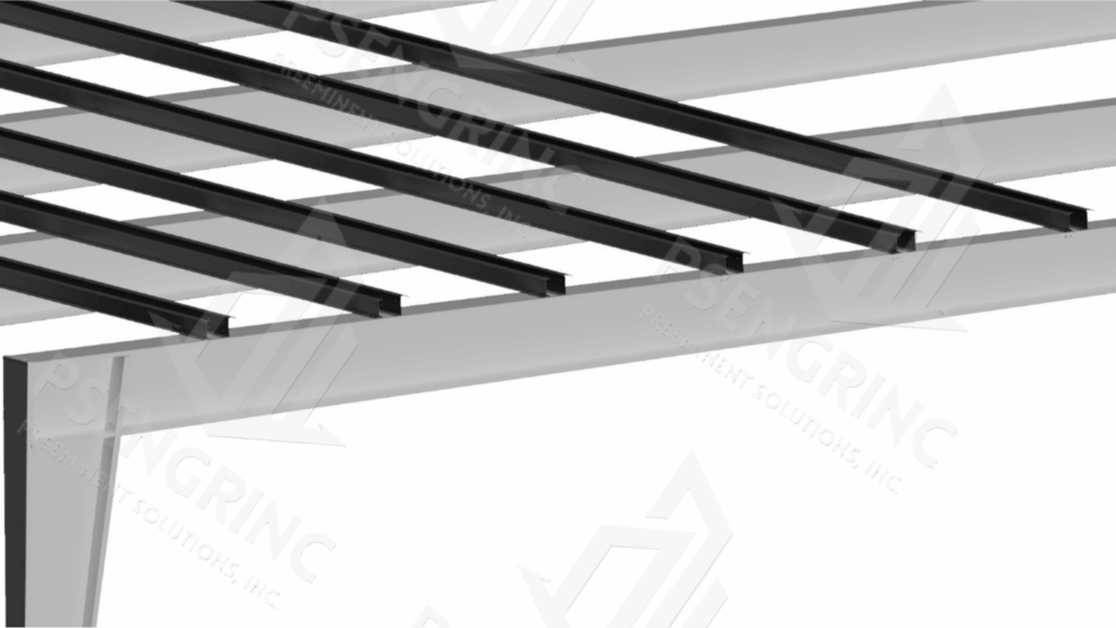
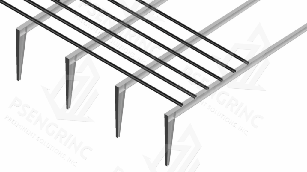
The primary roof structure consists of a portal frame system spanning approximately 200 feet in the east–west direction. The roof is constructed of metal decking with a membrane roofing system, supported by secondary purlins spanning between the main rafters with an average spacing of about 25ft. The load path transfers from the roof sheeting to the purlins, then to the rigidly connected rafters and columns, and ultimately to the foundations.
The roof structure is the primary area of interest for this investigation, as the proposed upgrades to the fire suppression system introduce additional piping loads supported directly on the purlins. These members are therefore the critical elements evaluated in this analysis, since preliminary assessment indicated that the purlins are most susceptible to overstress and potential failure under combined existing and new piping loads.
1. Potential Future Load
Purlin Failure
The installation of the new fire suppression piping system imposes additional sustained dead load directly onto the existing roof purlins. The current roof system was designed to resist a combination of roof dead load (20 psf), collateral load (5 psf), and roof live load (20 psf). With the added piping load applied through clamp connections, the demand on the Z-section purlins (8Z3.25×105 at 5 ft spacing, spanning approximately 25 ft) increases significantly.
Analysis indicates that the purlins are the critical members most susceptible to overstress under the combined loading condition. Without structural modification, this condition presents a risk of progressive distress or failure of the purlins, which in turn could compromise the integrity of the roof system. Accordingly, evaluation of retrofit or strengthening options is necessary to ensure adequate performance under both existing and future load demands.
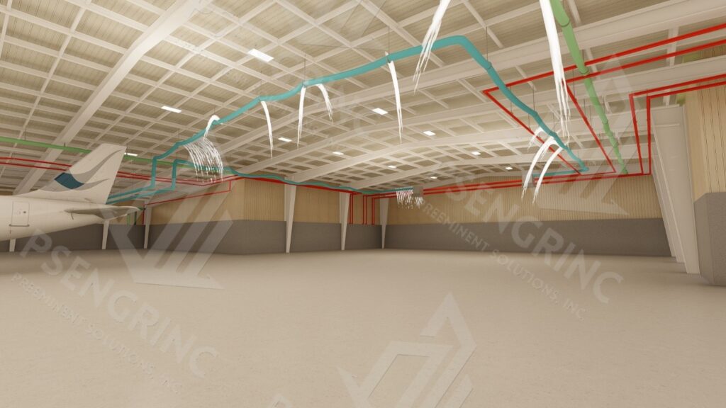
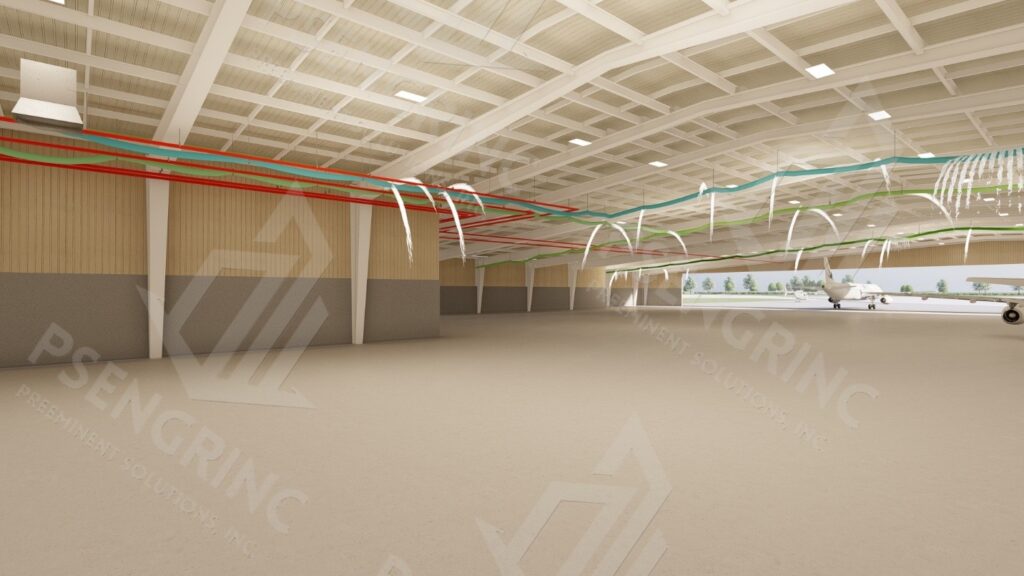
Pipe Failure
Potential failure of the fire suppression piping system in the hangar poses a structural risk to the roof. The piping, supported by clamps on the purlins, introduces sustained dead load that was not part of the original design. If the purlins become overstressed, they may deform or fail, leading to compromised support for the roof deck and the attached piping. Such failure could result in progressive collapse of roof sections and loss of fire protection capability.
2. Observations – Structural Analysis
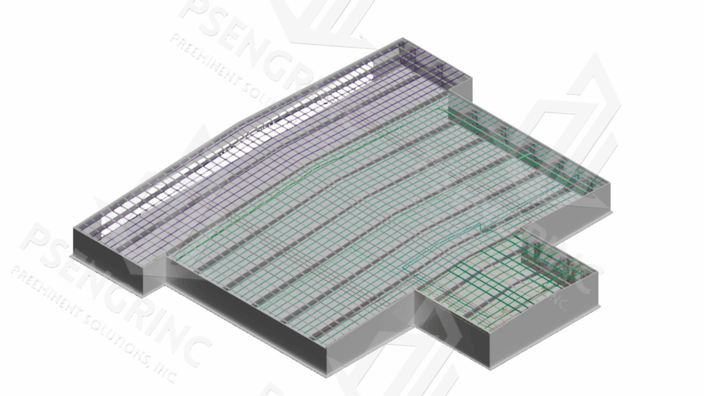
Finite Element Analysis (FEA) was employed to evaluate the performance of the purlins, portal rafters, and columns under combined roof and fire suppression piping loads. FEA is a computational method that simulates how structural components respond to applied forces, enabling accurate prediction of stresses, deflections, and potential failure modes.
The analysis incorporated both linear elastic behavior and P-Delta effects. The P-Delta analysis captures the interaction between axial load and lateral displacement, which can amplify internal forces and moments, particularly in slender columns and portal frame members. This approach was critical to assess the stability of the roof framing system under the additional sustained piping load.
FEA results were also used to extract reaction forces and load distribution across the purlins, confirming that the purlins are the most critical elements affected by the added fire suppression system loads.
Recommendations
There are multiple unknowns regarding the as-built conditions of the subject structure, including the precise material strengths, connection details, and in-place performance of existing members. However, based on observed conditions and structural analysis, the following deficiency-specific recommendations are provided:
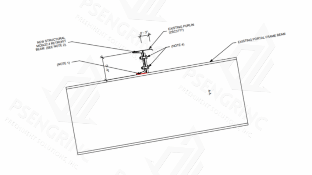
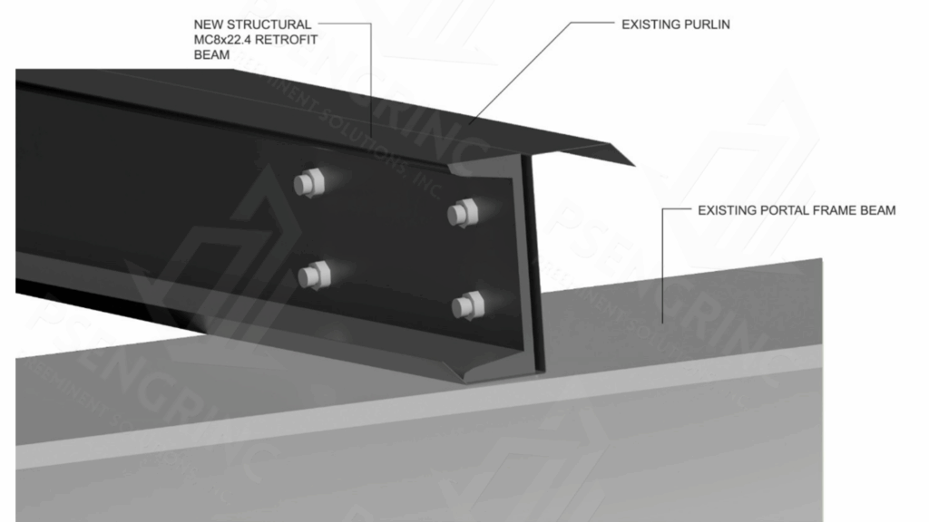
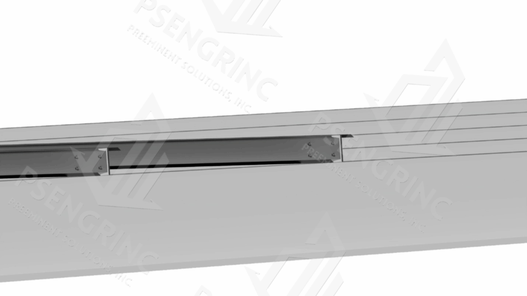
Option 1 – Retrofit Existing Z-Purlins with Cold-Formed Channel Section
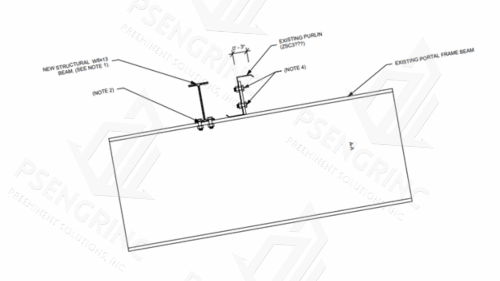
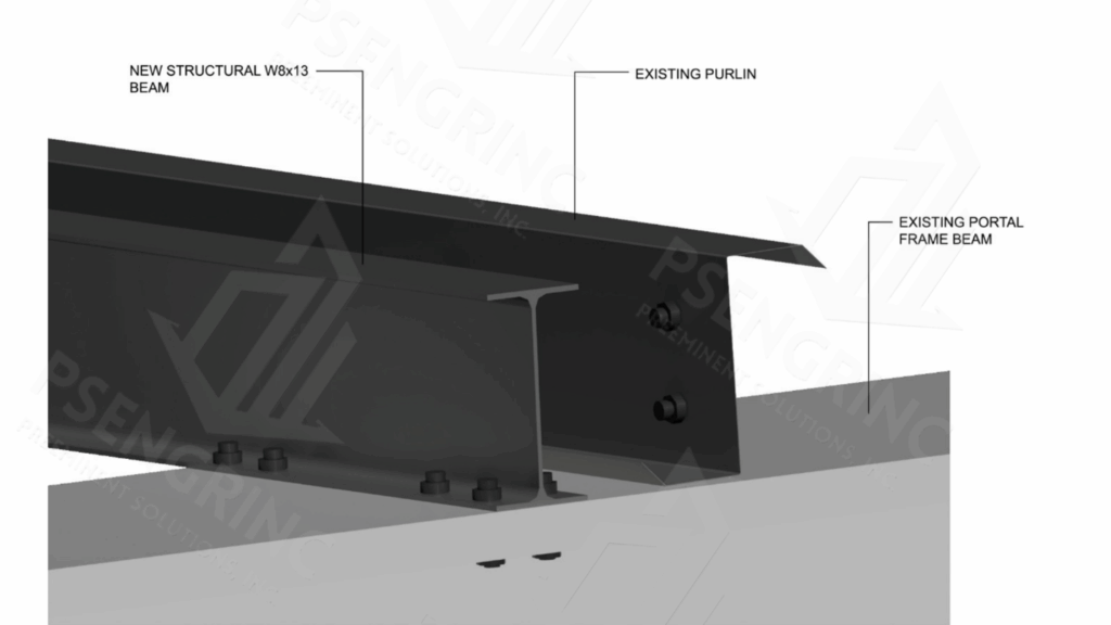
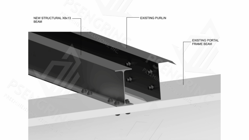
Option 2 – Install New Hot-Rolled Wide Flange Beam
General Notes
All retrofit work shall comply with AISC 360-22 and AISI S100-16 standards for cold-formed steel design.
Field verification of existing member sizes, thickness, and condition must be completed prior to installation.
Shop drawings and erection plans must be submitted for review prior to fabrication and installation.
Inspection and testing of connections shall be performed to confirm compliance with design intent and quality assurance standards.