AVATION RENDERINGS CASE STUDY
Introduction
Wall Opening and Retrofit
Preeminent Solutions, Inc. has been engaged to provide civil-structural engineering services for the retrofit of an existing interior masonry wall at the commercial facility.
The scope of this report includes the evaluation and design recommendations for creating a 9 ft x 9 ft (minimum) wall opening within the existing load-bearing masonry wall. The retrofit is intended to facilitate improved operational flow within the facility while maintaining the structural integrity of the existing building.
Based on preliminary site observations and available documentation, the existing wall system and surrounding framing appear to be generally sound; however, modifications of this magnitude require detailed structural review and reinforcement design to ensure adequate load transfer and compliance with current Florida Building Code requirements.
Further investigation, including review of available as-built drawings and confirmation of existing wall conditions, is recommended to finalize the retrofit design. Structural analysis will be performed to verify member capacities and determine the appropriate retrofit framing and lintel design for the new wall opening.
Problem Statement / Objectives
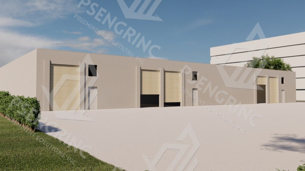
The subject property is a single-story commercial building of masonry construction. The structure consists primarily of concrete masonry unit (CMU) exterior and interior load-bearing walls supported on a reinforced concrete slab-on-grade foundation system.
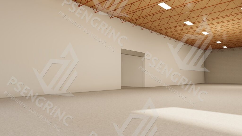
The building features a steel-framed roof structure with open-web steel joists and metal decking, supporting mechanically fastened roofing assemblies typical of light commercial facilities. The existing interior wall proposed for modification functions as a load-bearing partition supporting roof joists and lateral load transfer.
For the purpose of this report, the structural assessment and design recommendations are limited to the interior masonry wall designated for retrofit to accommodate a 9 ft x 9 ft (minimum) wall opening. The remainder of the structure was not included within the scope of this evaluation.
Analysis / Findings
• Structural Description – Wall Opening and Retrofit
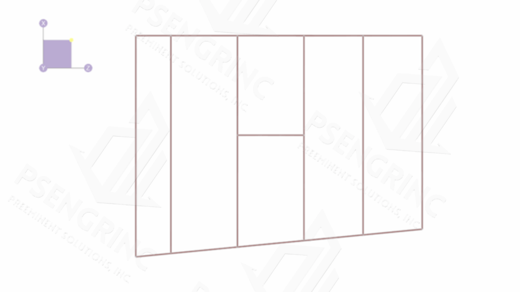
The proposed structural modification involves the creation of a 9 ft x 9 ft (minimum) opening within an existing interior load-bearing concrete masonry unit (CMU) wall. The wall serves as part of the building’s primary gravity and lateral load-resisting system, supporting the tributary roof joists and distributing vertical and lateral forces to the foundation.
Based on preliminary observations, the existing wall is constructed of 8-inch nominal CMU, reinforced vertically and horizontally in accordance with typical commercial construction practices. The wall bears directly on the reinforced concrete slab-on-grade foundation, with no apparent structural separation between adjoining bays.
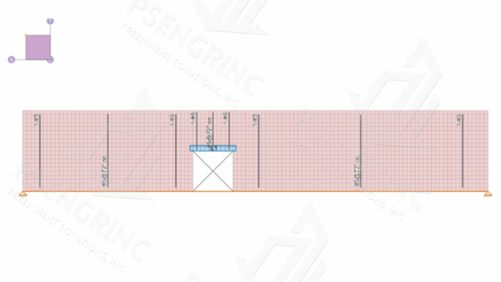
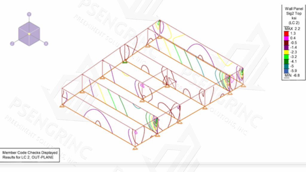
To maintain structural integrity after the wall opening is introduced, a retrofit framing system will be designed to redistribute loads around the new opening. The retrofit will likely consist of steel lintels or a structural steel frame integrated into the existing CMU wall, anchored to adjacent masonry and supported at the foundation level as required by structural analysis.
The final retrofit configuration will be determined based on verification of existing wall reinforcement, joist bearing conditions, and as-built construction details. All retrofit design elements will comply with the applicable provisions of the Florida Building Code (FBC) and relevant structural standards including ACI 530/ASCE 5, AISC 360, and ASCE 7.
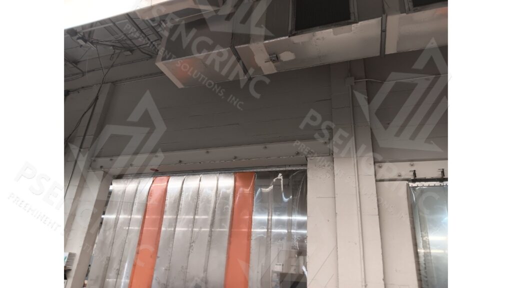
• Structural Description – Roof and Roof Framing System
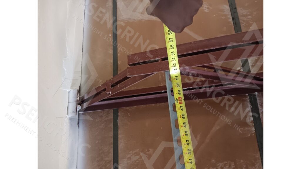
The roof framing system consists of open-web steel joists (K-series joists), approximately 28 inches in depth, spaced at roughly 3 feet 9 inches on center. The joists support a metal roof deck, which in turn carries the roofing assembly and associated mechanical loads. Typical joist panel spacing is approximately 2 feet along the span; however, conditions near wall bearings could not be directly verified at the time of inspection due to limited access and existing ceiling finishes.
Further field verification is recommended to confirm joist bearing details, bridging configuration, and end connection conditions, particularly in areas adjacent to the proposed wall opening.
1. Observations – Structural Analysis
Preeminent Solutions, Inc. performed an initial structural site inspection of the subject facility located at 1401 Sligh Blvd, Orlando, FL 32806, on March 26, 2025. The inspection was conducted to document existing conditions and assess the feasibility of introducing a 9 ft x 9 ft (minimum) wall opening within the existing interior masonry wall.
All directional references herein are given from the perspective of an individual facing due North, and all references correspond to true global directions.
The inspection and evaluation were performed in general accordance with the American Society of Civil Engineers (ASCE) Guidelines for Structural Condition Assessment of Existing Buildings (SEI/ASCE 11-99). Analysis and recommendations are based on applicable provisions of the following codes and standards:
- Florida Building Code – Building (8th Edition, 2023)
- Florida Building Code – Existing Building (8th Edition, 2023)
- ASTM E678-07 (Reapproved 2013) – Standard Practice for Evaluation of Technical Data
- ACI 530/ASCE 5/TMS 402 – Building Code Requirements for Masonry Structures
- AISC 360 – Specification for Structural Steel Buildings
These standards establish the technical basis for evaluating the condition and load capacity of existing structural systems to ensure public safety and code compliance.
No destructive testing, material sampling, or laboratory testing was conducted for this report. All findings are based on visual observation and non-destructive assessment performed at accessible locations.
2. Code Violations and Key Areas of Interest
This report addresses the inspection and evaluation of the existing interior masonry wall designated for retrofit to accommodate a 9 ft x 9 ft (minimum) wall opening. The purpose of the evaluation is to ensure that the proposed modification complies with applicable provisions of the Florida Building Code (FBC, 8th Edition – 2023) and associated structural standards governing alterations to load-bearing systems.
Key areas of interest include the assessment of load transfer, adequacy of existing reinforcement, and stability of the surrounding structure following the introduction of the new opening. Special consideration is given to compliance with FBC Chapter 16 (Structural Design) and Chapter 34 (Existing Buildings), which outline performance requirements for structural alterations.
The retrofit design will provide appropriate lintel framing and anchorage details to maintain structural continuity and code compliance throughout the modified wall section.
Recommendations
Site
The subject site at 3155 S John Young Pkwy, Orlando, FL 32805 (Parcel ID: 04-23-29-0000-00-045) is partially situated within a Special Flood Hazard Area according to Federal Emergency Management Agency (FEMA) data (see Appendix F).
According to U.S. Geological Survey (USGS) records for the nearest groundwater monitoring station (USGS 282835081305201 – Palm Lake Drive Well near Windermere, FL at coordinates 28°28′39″ N, 81°30′26″ W), the land surface elevation is reported at 158.69 ft above NGVD 29.
Based on the survey documents for the subject building, the base floor elevation is given as 96.3 ft NAVD 88. This elevation places the finished floor level approximately 18.82 ft above the estimated maximum groundwater elevation inferred from the USGS station (after datum conversion), assuming the groundwater in this region would not exceed the historic highest levels recorded at the reference USGS well.
Given the distance between the subject site and the groundwater station, and uncertainties in datum conversion and local hydrogeology, the assumed groundwater levels should be treated as preliminary estimates. Final geotechnical or local hydrologic investigation is recommended to confirm actual site groundwater conditions.
Per the survey documents for the structure, the base floor elevation is 96.3 ft NAVD88, roughly 18.82 ft higher than the maximum ground water level of the nearest USGS ground water station.
There are multiple unknowns with the subject structure.
Further inspection, testing, and/or review of original structural drawings and as-built structural drawings is required to attain pertinent data for more accurate recommendations.
Roof and Roof Truss System

The following recommendations are advised to address the aforementioned deficiencies.
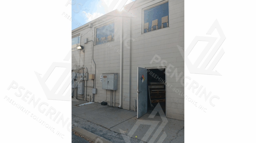
- Opening in Roofing Membrane Near Main Roof Entry Door
- Blistering in Built Up Roof System
- Ponding Water on Built Up Roof System
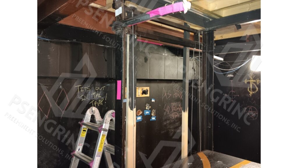
Tunnel
Major and minor cracking was observed throughout the tunnel and its auxiliary rooms.
As a general note, further inspection and testing is advised to attain pertinent data to determine appropriate repair method(s) needed to address the observed deficiencies.
- Stepwise Cracking in Masonry Walls, South Interior Face of Tunnel
- Vertical Chip in Masonry Walls, North Interior Face of Tunnel
Tunnel / Basement Laundry Area
- Stepwise Cracking in Masonry Walls, South West Interior Face of Laundry Area
- Hairline Cracking Along Ceiling Slab Laundry Area
- Shear Cracking in R/C Concrete Slab
- Plaster Spalling Near Laundry Area, South Interior Face of Tunnel, Near Laundry Room
Tunnel Auxiliary Rooms
- Stepwise Cracking in Masonry Walls, South Interior Face of Tunnel Auxiliary Rooms
- Alteration / Removal of Section of Interior Tunnel Wall
Conclusions
The subject structure displays several key structural deficiencies. Deficiencies include failure of building envelope via roof opening and major cracking along laundry room equipment slab / foundation slab. It is advised to address these deficiencies as soon as possible.
Due to the degree of unknowns, further inspection, testing, and/or review of original structural drawings and as-built structural drawings is required.
Likewise, due to the degree of deficiency, structural analysis is advised prior to major repair and retrofit.
It is advised to comply with the above recommendations to resolve the above deficiencies as soon as possible.