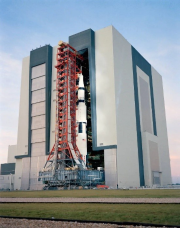
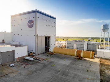
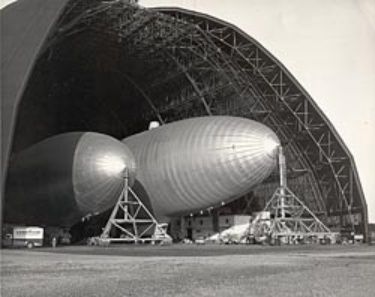
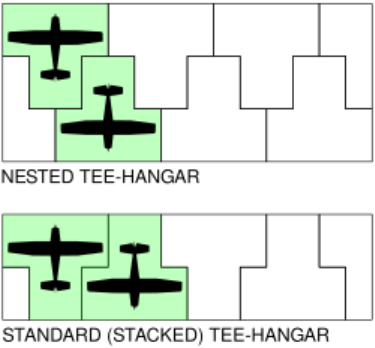
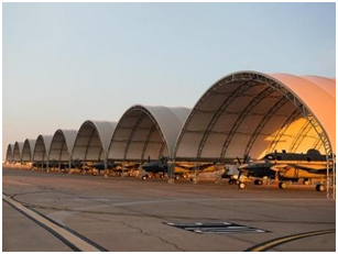
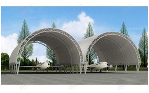
Aircraft/spacecraft hangars (also known as “hangars”) include buildings or structures designed to maintain, store, and protect aircraft (i.e. commercial aircraft, military aircraft, planes, helicopters, etc.) and/or spacecraft (i.e. launch vehicles, crewed vehicles, robotic probes, etc.) Hangars are structurally distinct structures known for their enormous size, massive clear-span framing, colossal doors, enhanced fire suppression systems, and heavily reinforced foundations.
Famous aircraft/spacecraft hangars include: NASA’s Kennedy Space Center (KSC) Vehicle Assembly Building (VAB), in Merrit Island, FL; NASA’s Marshall Space Flight Center (MSFC) Michoud Assembly Facility (MAF); the Cape Canaveral Space Force Station Hangar S (aka. “Cradle of Human Spaceflight”); and the Goodyear Airdock in Akron, OH.
Aircraft hangars are generally classified based on functionality and with respect to National Fire Protection Association (NFPA) Standard on Aircraft Hangars, NFPA 409. Key NFPA 409 Fire Protection Classifications include:
Group I: Largest facilities; single fire area of 40,000 sq ft (3,716 sq m), or more
Group II: Medium-sized facilities; single fire area between 12,001 and 40,000 sq ft.
Group III: Smaller facilities; single fire area of 12,000 sq ft or less.
Group IV: Specific membrane-covered, rigid steel frame structures.
Key Functional & Design Aircraft Hangar Classifications include:
T-Hangars
Box / Community Hangars
Maintenance, Repair, and Overhaul (MRO) Hangars
Corporate / Fixed Base Operator (FBO) Hangars
Military Hangars
Similarly, spacecraft hangars are classified by their operational environment (terrestrial vs. extraterrestrial), functionality, and scale.
Key Functional & Design Spacecraft Hangar Classifications include:
Vertical Assembly / Integration Hangars: (i.e., the Vehicle Assembly Building).
Horizontal Processing Hangars
Mobile Service / Transport Hangars
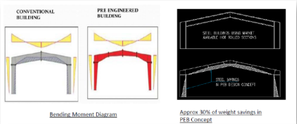
Pre-Engineered Vs Conventional Buildings | Tata Steel Colors
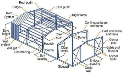
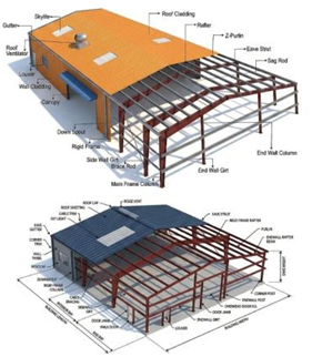
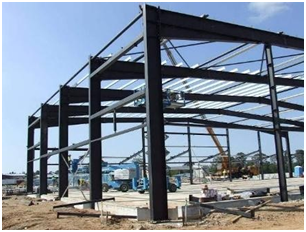
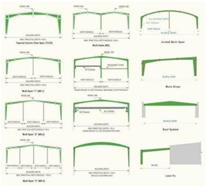
Hangars include Reinforced Concrete structures (i.e. hardened hangars), Pre-Engineered Metal Buildings (PEMBs), and conventional steel buildings (CSBs). That said, due to their size and complexity – which includes large clear-span roofs, oversized doors, high wind exposure, fire-protection complexity, aircraft fuel hazards, corrosion exposure, crane/hoist loads, and operational impact risks – hangars have distinct design requirements.
Governing aircraft / spacecraft hangar design codes and standards include the International Building Code (IBC), the American Society of Civil Engineers (ASCE), “Minimum Design Loads and Associated Criteria for Buildings and Other Structures” (ASCE 7), the American Institute of Steel Construction (AISC) Steel Construction Manual, the American Concrete Institute (ACI) Building Code Requirements for Structural Concrete (ACI 318), the National Fire Protection Association (NFPA) Standard on Aircraft Hangars, (NFPA 70). Similarly, while aircraft hangars must also comply with Federal Aviation Administration (FAA) Advisory Circulars (AC 150/5300) and local airport authority minimum standards, spacecraft hangars must comply with the Unified Facilities Criteria (UFC) Standards UFC 4-211-01N / UFC 4-211-01 and other applicable codes.
For Construction-Defect Defense Litigators, ascertaining the causation, and thus liability of a construction defect, while avoiding technical blindsides and reigning in projected costs can be a daunting process. This is most notable for litigators seeking causation for construction and design standard-of-care violations, and those seeking causation for code violations and defective material quality.
For construction or design defects involving major components it is generally advisable to engage construction-defect experts early on in the case to determine causation, reduce risks, and limit costs.
Particularly, for construction or design defects involving structural components it is generally advisable to engage construction-defect and structural forensic engineering experts early on in the case to determine causation, reduce risks, and limit costs.
Below are the top 5 structural blind spots in Hangar Renovation for Construction-Defect Defense Litigators.
For construction defects or design defects involving structural components it is generally advisable to engage construction-defect and structural forensic engineering experts early on in the case to determine causation, reduce risks, and limit costs.
Preeminent Solutions is a WOSB-certified, DBE-certified, MWBE-certified, LDB-certified and soon-to-be 8(a)-certified and civil/structural engineering firm specializing in structural forensics and construction-defect expert witness work.
Contact us for your next aircraft and/or spacecraft hangar construction-defect case.
Long-Span Beam/Girder Distress
Hangars house a variety of large-scale aircraft and/or spacecraft vehicles, ranging from hot air balloons to rockets. As a consequence, hangars must employ ample space, broad roofs, and large openings: conditions that are best supported by long-span members.
Long span members include structural elements—such as beams, trusses, or girders—designed to bridge large distances without requiring middle supports or columns.
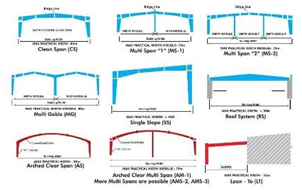
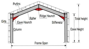
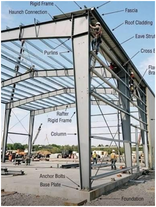
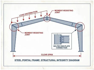
Hangars typically employ long-span members, arches, cables, portal frames, rigid frames, and/or space frames to create unobstructed aircraft bays.
That said, due to the long spans, such systems are especially sensitive to key issues including:
• Corrosion
• Connection Issues
• Excessive Deflection
• Excessive Vibration Loads
• Excessive Roof Ponding Loads
• Roof Overload (i.e. due to fire suppression systems or other additional weight.)
• Unexpected Suspended Loads (i.e. due to Crane Loading, etc.)
• Transport and Erection During Construction
Key signs of structural overload in long-span steel beams/girders include:
- Excessive Sagging, particularly at the mid-span
- Web Buckling
- Flange Distortion or Bending
- Excessive Movement under Lateral Loads
- Lateral-Torsional Buckling (i.e. Twisting of the Beam Member)
- Web Crippling, near Columns
- Cracked Welds
- Sheared-Off or Broken Bolts
- Loosened Nuts
- Elongated Bolt Holes
- Gusset Plate Distortion
• Unexpected Suspended Loads (i.e. due to Crane Loading, etc.)
• Transport and Erection During Construction
Key signs of structural overload in long-span steel beams/girders include:
• Excessive Sagging, particularly at the mid-span
• Web Buckling
• Flange Distortion or Bending
• Excessive Movement under Lateral Loads
• Lateral-Torsional Buckling (i.e. Twisting of the Beam Member)
• Web Crippling, near Columns
• Cracked Welds
• Sheared-Off or Broken Bolts
• Loosened Nuts
• Elongated Bolt Holes
• Gusset Plate Distortion
Due to the relatively limited degree of redundancy in long-span systems, smaller issues should be addressed immediately to avoid magnification into larger issues, particularly with connection issues between long-span beams and the supporting frame members.
Key signs of structural overload in portal frames include:
• Excessive Mid-span Beam Sagging
• Beam Web Buckling
• Beam Flange Distortion or Bending
• Excessive Movement under Lateral Loads
• Beam Lateral-Torsional Buckling (i.e. Twisting of the Beam Member)
• Local Beam Web Crippling near Concentrated Crane Loads
• Out-of-Plumb Columns
• Bowing Columns
• Local Web Crippling near Concentrated Lateral Loads
• Local Flange Buckling
• Twisted Girts
• Severe Cracking or spalling Near Concrete Plinths/Grout Pads.
Note: Structural overloading is a serious risk to life and public safety. As a consequence, it must be addressed as soon as possible. Contact a qualified structural engineer immediately if your structure displays any of the above signs of overloading.
Consult Preeminent Solutions’ Free Online Education Center for resources and checklists regarding structural overloading issues:
Link: https://psengrinc.com/learning/
Contact a qualified structural engineer if your structure displays any of the above signs of overloading.
Floor Vibration and Seismic Equipment Fragility
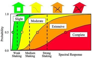
Hangars in seismically active areas must be designed and/or retrofitted with seismic fragility, anchorage fragility, and equipment fragility in mind. Designs include consideration for floor vibration and equipment fragility.
Note: Seismic fragility basically refers to the likelihood that a structure will suffer damage when hit by an earthquake of a certain level of strength. Likewise, anchorage fragility basically refers to the likelihood that anchorage will fail when hit with an external load. Lastly, equipment fragility basically refers to the likelihood that a piece of equipment, equipment support, and/or equipment anchorage will fail and/or lose function when hit with an external load.
Key signs of inadequate equipment supports or equipment anchorage in high seismic areas include:
• Inadequate Anchor Edge Distance (in Concrete and Masonry Supports)
• Inadequate Anchor Embedment Depths (in Concrete and Masonry Supports)
• Shallow and/or Non-Monolithically Poured Concrete Equipment Pads
• Non-seismic Connectors and Fasteners
• Unreinforced or Under-reinforced Masonry and/or Concrete Walls
Key signs of seismic damage include:
• Diagonal Cracking in Concrete Walls
• Diagonal Cracking in Concrete Beams
• Concrete Crushing of at the Base of Columns
• Concrete spalling at Column-Beam joints
• Concrete spalling at Frame Corners
• Localized flange and/or Web Buckling in Steel Columns
• Localized flange and/or Web Buckling in Steel Beams
• Distortion of Gusset Plates, Bolts, and Connections
• Sheared Bolts at Moment-Frame Connections
• Torn Bolts at Braced-Frame Connections
Consult Preeminent Solutions’ Free Online Education Center for resources and checklists regarding seismic damage:
Link: https://psengrinc.com/learning/
Contact a qualified structural engineer if your structure displays any of the above signs of seismic damage
Foam Fire-Suppression Retrofit Impacts
Hangars encompass exceptionally massive building footprints and are typically comprised of 1 or more Hangar Fire Areas.
Per NFPA 409 guidelines, Hangar Fire Areas include areas within the hangar storage and servicing area, subject to loss by a single fire due to lack of internal subdivisions as specified within the code.
Such large hangar areas require large, distributed fire protection systems to protect life and property.
Per NFPA 409, hangars shall utilize one of the following fire protection strategies within storage and service areas:
- A Prescriptive Approach (i.e. the use the fire protection and life safety systems)
- A Fire-Risk-Based Approach
- A Performance-Based Design Approach
For existing hangars, designers and builders may utilize Foam Fire Suppression Systems in accordance with the NFPA prescriptive approach.
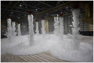
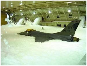
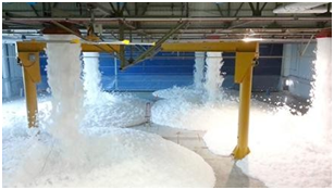
Foam Fire Suppression Systems include specialized fire protection systems that discharge a low-density mix of water, foam concentrate, and air to arrest fires and suppress vapor release to prevent reignition.
Many aircraft hangars require specialized foam and/or fire-suppression systems due to fuel hazards.
Foam Fire Suppression Systems may include large pipe mains, foam systems, deluge piping, tanks, pumps, and suspended pipe networks. Retrofit updates can add additional tanks, piping, containment systems, and support platforms to existing hangars. Depending on the configuration, such additions to the Foam Fire Suppression System may impart significant loads unto the hangar roof system.
Key loads from Foam Fire Suppression Systems unto hangar roof structures include:
- Piping Weight (Dry Lines)
- Piping Weight with Water Loads (Wet Lines Only)
- Sway Bracing Loads (i.e. Loads Under Seismic, Wind, or Other lateral Loads)
- Thrust and Reaction Forces, namely at Pipe Bends, Tees, and End-of-Line Sections
Due to the abundance of long-span elements and limited redundancies, excessive loads from Foam Fire Suppression can negatively impact hangar roof structural elements.
Key structural warning signs of hangar roof overload due to Foam Fire Suppression loading include:
- Sagging or Bowing in Roof Trusses
- Sagging of Rafter Beams
- Sagging Roof Decks at Perimeter
- Loose or Buckling Cross-Bracing
- Cracked Welds
- Sheared Connection Bolts
- Torn or Elongated Gusset Plates
Likewise, depending on the configuration, Foam Fire Suppression Systems can impart significant loads unto the hangar vertical elements (i.e. the columns, and portal frames).
Key structural warning signs of hangar column overload due to Foam Fire Suppression loading include:
- Slippage or Shear deformation in Bolted Rafter-to-Column
- Out-of-Plumb Columns (Extreme Cases)
- Column Base Plate Uplift or Deformation
- Column Pedestal Cracking (Extreme Cases)
- Cracked Welds
- Sheared Connection Bolts
- Torn or Elongated Gusset Plates
The above issues are especially relevant in the retrofit of older structures.
Consult Preeminent Solutions’ Free Online Education Center for resources and checklists regarding roof overloading issues:
Link: https://psengrinc.com/learning/
Contact a qualified mechanical engineer and/or fire suppression specialist if your structure displays any issues with the fire suppression system.
Contact a qualified structural engineer if your structure displays any of the above signs of structural overloading or other structural issues.
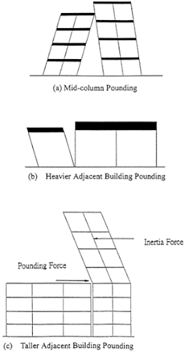
Seismic Joint and Pounding Risk
Earthquakes impart tremendous loads unto the members, foundations, connections, and joints of building structures. As a consequence, poor seismic design and retrofit pose an imminent threat to life and public safety.
Note: Seismic joints include intentional-designed gaps between distinct sections of the same structure that allow the different parts to move independently during an earthquake. One of the purposes of a seismic joint is to prevent structural pounding and/or major structural damage.
Per the 2024 International Building Code (IBC) Code and ASCE 7-22, the governing codes on the matter at time of this publication, in seismic-prone regions, engineers shall design seismic joints to allow for the minimum design earthquake displacements
in accordance with the code.
Key signs of inadequate seismic joint spacing risk and seismic pounding risk include:
- Narrow or Minimal Gap Between Adjacent Wings of Structure
- Misaligned Adjacent Floor Diaphragms (i.e. Diaphragms sitting at different heights, thus the slabs of one structure impact the columns of the other)
- Exaggerated Discrepancy in Adjacent Structures’ Height and Design (i.e. Tall, Slender juxtaposed to short, stout structures.)
Key signs of inadequate seismic joint spacing and seismic pounding
- Fracturing or Crushing of Concrete at the corners of floor slabs and/or beam edges at the corners facing the seismic joint
- Severe Diagonal Cracking in Exterior Columns at the corners facing the seismic joint
- Chipping, or crushing Concrete Masonry Units (CMUs) or Brick at the corners facing the seismic joint
Consult Preeminent Solutions’ Free Online Education Center for resources and checklists regarding seismic damage:
Link: https://psengrinc.com/learning/
Contact a qualified structural engineer if your structure displays any of the above signs of seismic pounding
Sulfate Attacks
Hangars protect and support large aircraft and spacecraft vehicles that routinely apply tremendous, concentrated loads unto the foundation slabs.
For example, the typical Boeing 767 commercial airliner vehicle applies over 50,000 lbs of concentrated load per each of its 6 main wheels while taxiing.
Hangar slabs must be designed to withstand such high and concentrated loads without failure.
Likewise, hangar slabs must be able to withstand such loading in otherwise unfavorable environmental conditions without failure.
Frequently hangar new-builds and/or pre-existing structures are situated on sites with high-risk for sulfate attack.
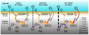
Sulfate attacks include chemical reactions between hardened concrete and sulfate-rich soils, groundwater, or seawater.
Sulfate attacks encompass the reaction of the water-soluble sulfates with the cement paste within concrete resulting in cracking, decreased strength, and overall deterioration of the concrete.
Per ACI 318 Building Code Requirements for Structural Concrete, the governing code on the matter at time of this publication, there are four (4) distinct sulfate exposure severity classifications:
- S0 (Negligible): Soil SO₄ < 0.10%, Water SO₄ < 150 ppm — No special cement requirements
- S1 (Moderate): Soil 0.10% ≤ SO₄ < 0.20%, Water 150 ≤ SO₄ < 1500 ppm (includes seawater) — Requires sulfate-resistant cement
- S2 (Severe): Soil 0.20% ≤ SO₄ ≤ 2.00%, Water 1500 ≤ SO₄ < 10,000 ppm — Requires sulfate-resistant cement
- S3 (Very Severe): Soil SO₄ > 2.00%, Water SO₄ > 10,000 ppm — Requires sulfate-resistant cement and additional measures.
Regardless of the sulfate exposure severity classification, hangar slabs must be able to withstand unfavorable environmental conditions, including sulfate-rich environments without failure.
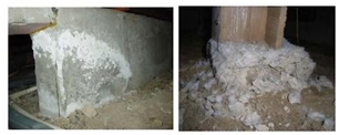
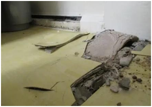
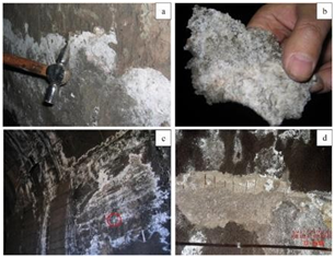
Key signs of concrete foundation slab failure due to sulfate attacks include:
- Concrete Efflorescence
- Severe Mapped Cracking Along Slab Surface
- Severe Cracking in Connected R/C Wall Elements
- Slab Expansion and/or Heaving
- Sloping and/or Uneven Floors
- Concrete Crumbling
- Concrete Spalling
Concrete is a porous material. In monolithically poured slab/stem wall structures dissolved sulfates can travel and affect associated stem walls. This is most pertinent during flood-like conditions.
Key signs of concrete stem wall failure due to sulfate attacks include:
- Severe Wall Cracking
- Concrete Efflorescence
- Rust stains
- Bowing or Out-of-Plumb Walls
- Wall-to-Frame Separation
- Concrete Crumbling
- Concrete Spalling around Rebar
Consult Preeminent Solutions’ Free Online Education Center for resources and checklists regarding structural deterioration issues:
Link: https://psengrinc.com/learning/
Contact a qualified structural engineer if your structure displays any of the above signs of sulfate attacks.
Preeminent Solutions is a DBE-certified, MWBE-certified, LDB-certified and soon to be 8(a)-certified and WOSB-certified, civil/structural engineering firm.
We have over 30 years’ experience in civil/structural design, forensics, and expert work
We’re Licensed in CA, FL, TX, NJ, NY, DC, MD, VA, TN, MS, GA, NC, SC, LA, & more.
Reach out if your team is in need of structural engineering support.
Preeminent Solutions, Inc.
Forensic Structural Engineers & Consultants
📞 (321) 244-8699 | (407) 901-0133
✉️ info@psengrinc.com
🌐 www.psengrinc.com
Author
-
Vanessa Malone, P.E. is the Owner of Preeminent Solutions, Inc.
She is a licensed civil / structural engineer with almost 15 years’ experience in civil/structural design, forensics, and expert work.
She is licensed in Florida, California, Texas, Washington D.C., Virginia, Maryland, New York, New Jersey, Louisiana, Georgia, Mississippi, North Carolina Tennessee, and several other states and territories.
She has worked with Thornton Tomasetti, Westinghouse, NASA, NOAA, the Navy, Southern Nuclear, General Electric, Bechtel, and other companies.
Malone is a first generation American. She first emigrated to the continental United States almost 20 years ago.
Malone shares her love of engineering through her company and through her interactions with other firms.
Thank you and we look forward to serving you!